Addressing and baud rate settings, Zone, Figure 4: gpc-xp controller address switch setting – Orion System GPC-XP Controller User Manual
Page 8: Ao ut 1 -2, Baud rate selection
Zone
Zone
Section 1: GPC-XP Wiring & Setup
GPC-XP Controller Technical Guide
8
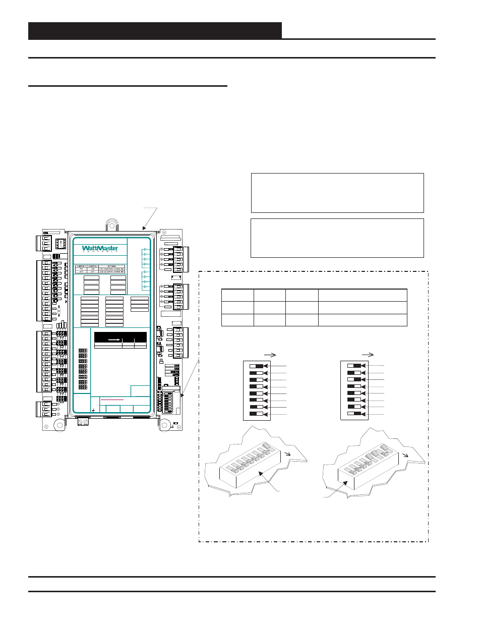
Controller Addressing and Baud Rate
The GPC-XP Controller is equipped with address switches. When
using Prism 2 to program and confi gure the GPC-XP Controller, you
would enter this address to communicate with the controller. When
the system is to be connected to other HVAC unit controllers on a
communication loop, each controller’s address switch must be set
with a unique address between 1 and 59.
Figure 4: GPC-XP Controller Address Switch Setting
GPC-XP Controller
16
32
Baud 0
Baud 1
8
4
2
1
Address Switch Shown Is
Set For Address 1
Address Switch Shown Is
Set For Address 13
Controller
Address Switch
Note:
The Power To The Controller Must Be Removed And
Reconnected After Changing The Address Switch
Settings In Order For Any Changes To Take Effect.
Caution:
Disconnect All Communication Loop Wiring From The
Controller Before Removing Power From The Controller.
Reconnect Power And Then Reconnect Communication
Loop Wiring.
Address 1 @ 9600 Baud
ADD
ADD
ADD
The Address For Each Controller
Must Be Unique To The Other Controllers
On The Local Loop And Be Between 1 and 59
CO
M
F
R
O
M
G
ND
CUT
TO
IS
O
L
A
T
E
WATTMASTER CONTROLS
YS102432 REV 3
LOOP COMM
GND
+24V
+5V
OUTPUTS
ADDRESS
ADD
1
2
4
8
16
32
POWER
EBUS
STATUS2
STATUS1
OUTPUTS
ANALOG
SERIAL #
OUTPUTS
RELAY
SH
R+
T-
BIN8
BIN7
BIN6
BIN5
BIN4
BIN3
BIN2
BIN1
BINARY
INPUTS
INPUTS
ANALOG
0-5
v
0-10
v
4-
2
0
m
A
AO
UT
1
-2
C14
R109
TB8
U19
U17
TB7
TB6
TB4
TB3
TB2
TB1
SW1
R97
R74
R6
1
R59
R5
5
R51
R47
R4
3
R4
1
R3
8
R21
R16
R14
D13
D12
D10
D9
D8
D7
D6
C46
C36
C21
RLY1
RLY2
RLY3
RLY4
COMMON
MADE IN USA
RLY1
RLY2
RLY3
RLY4
COMMON
AOUT1
AOUT2
AOUT3
AOUT4
GND
GND
1002
1002
.1uF
.1uF
AO
UT
3
-4
GND
1002
1002
1002
1002
1002
1002
1002
1002
1002
1002
1002
1002
.1uF
.01uF
LO
O
P
BAU
D
1
2
AI7
AI8
AI6
AI5
AI4
AI1
AI2
AI3
GND
GND
GND
GND
AI8
AI7
AI6
AI5
AI4
AI3
AI2
AI1
TH
E
R
M
VDC
300
300
300
300
300
300
300
300
COM
COM
COM
COM
D11
CONNEC
ON BOA
COMMLI
BAUD RATE SELECTION
Switch 7 Switch 8
9600
Baud
57600
OFF
OFF
ON
OFF
16
32
Baud 0
Baud 1
8
4
2
1
Address 5 @ 57,600 Baud
ADD
CommLink IV
Communication Setting
CommLink 5 & Stand Alone
RELAY CONTACT
RATING IS 1 AMP
MAX @ 24 VAC
RS-485 COMMUNICATION LOOP. WIRE
“R” TO “R”, “T” TO “T” “SHLD” TO “SHLD”
RELAY 2
RELAY 6
RELAY 1
RELAY 5
RLY 1 =
VDC
OUTPUTS
AI1 =
+ 24 VDC
+ 5 VDC
GND
BI1 =
AO1 =
AI2 =
BI2 =
AO2 =
AI3 =
BI3 =
AO3 =
AI4 =
BI4 =
AO4 =
AI5 =
BI5 =
AI6 =
BI6 =
AI7 =
BI7 =
AI8 =
BI8 =
RLY 2 =
RLY 5 =
RLY 3 =
RLY 6 =
RLY 4 =
RLY 7 =
RLY 8 =
RELAY 3
RELAY 7
RELAY 4
RELAY 8
COMMON
COMMON
USB
PORT
E-BUS
PORT
NOTES:
1.) ANALOG INPUT JUMPER SETTINGS MUST BE
SET FOR YOUR SPECIFIC INPUT DEVICE
REQUIREMENT.
2.) IT IS RECOMMENDED THAT YOU WRITE THE
DESCRIPTION OF THE INPUT, AND/OR
OUTPUTS YOU ARE CONNECTING TO THE
CONTROLLER IN THE BOXES PROVIDED ABOVE
USING A PERMANENT MARKER (SHARPIE) FOR
FUTURE REFERENCE.
®
24 VAC POWER ONLY
WARNING! POLARITY MUST BE OBSERVED
OR THE CONTROLLER WILL BE DAMAGED
www.wattmaster.com
AI1
AI2
AI3
AI4
AI5
AI6
AI7
AI8
THE
R
M
4-20
mA
0-
10
V
0-
5V
ANALOG
INPUT
JUMPERS
LED BLINK CODES
LED NAME
STATUS1
STATUS2
NORMAL OPERATION
0
1
SCHEDULE OVERRIDE
0
2
OE338-23-GPC-XP
GPC-XP CONTROLLER
WattMaster Label
#LB102095
Rev.: 1C
+2
4
VA
C
GND
Address switches 7 and 8 are used for the baud rate selection. See
Figure 4
below
for address switch and baud rate setting information.
Addressing and Baud Rate Settings