Troubleshooting the pt-link controller – Orion System PT-Link II LON User Manual
Page 15
PT-Link II Interface
PT-Link II LON
®
Technical Guide
15
Troubleshooting the PT-Link Controller
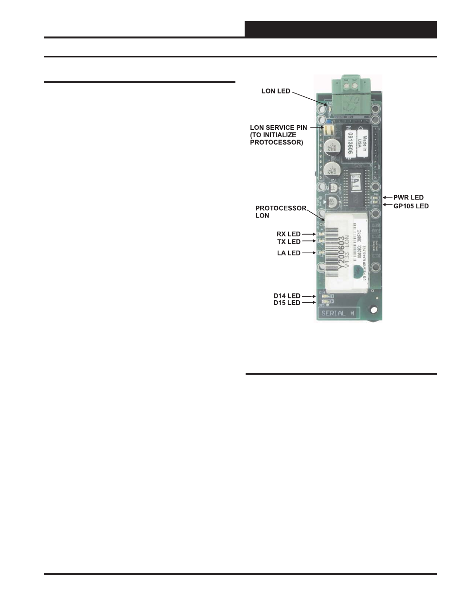
Figure 21: PT-Link II LON
®
LED Locations
ProtoCessor Module LEDs
PWR LED
When the PT-Link II is fi rst powered up, the “PWR” LED should light
up and stay on continuously. See Figure 21. If the LED doesn’t light up,
check that the ProtoCessor is installed correctly and fi rmly connected
to the Base Board.
GPI05 LED
The “GPI05” LED will light up when the Base Board and the ProtoCes-
sor Module have established communications. See Figure 21. This can
take up to 3 minutes depending on the number of units connected to
the PT-Link II . If it fails to light up after 3 minutes, check that the
ProtoCessor is installed correctly and fi rmly to the Base Board.
LON LED
Once the unit is powered up, the “LON” LED will blink continuously
until the PT-Link II has been commissioned. Once commissioned, the
“LON” LED will remain off.
LA LED
Once the unit is powered up, the “LA” LED must be blinking constantly.
See Figure 21. If this LED is constantly on or off, the Module is not
working properly and needs to be replaced.
TX & RX LEDs
The “TX” and “RX” LEDs work together to indicate that communication
is being established with the desired protocol network. If both LEDs
are blinking, then communication is working properly. See Figure
21. If not, check the protocol network wiring and the baud rate in the
confi guration fi le.
D14 & D15 LEDs
The “D14” and “D15” LEDs work together to indicate that commu-
nication is being transmitted and received from the USB Port when
performing an update to the PT-Link II software.
If all of these tests are made and the controller still doesn’t operate,
please contact WattMaster Controls Technical Support at our Toll Free
number—866-918-1100—for assistance.
Revised 1/5/11