Connection and wiring information, Pt-link ii interface, Pt-link ii lon – Orion System PT-Link II LON User Manual
Page 5: Technical guide 5, Figure 2: pt-link ii lon, Interface, Wiring
PT-Link II Interface
PT-Link II LON
®
Technical Guide
5
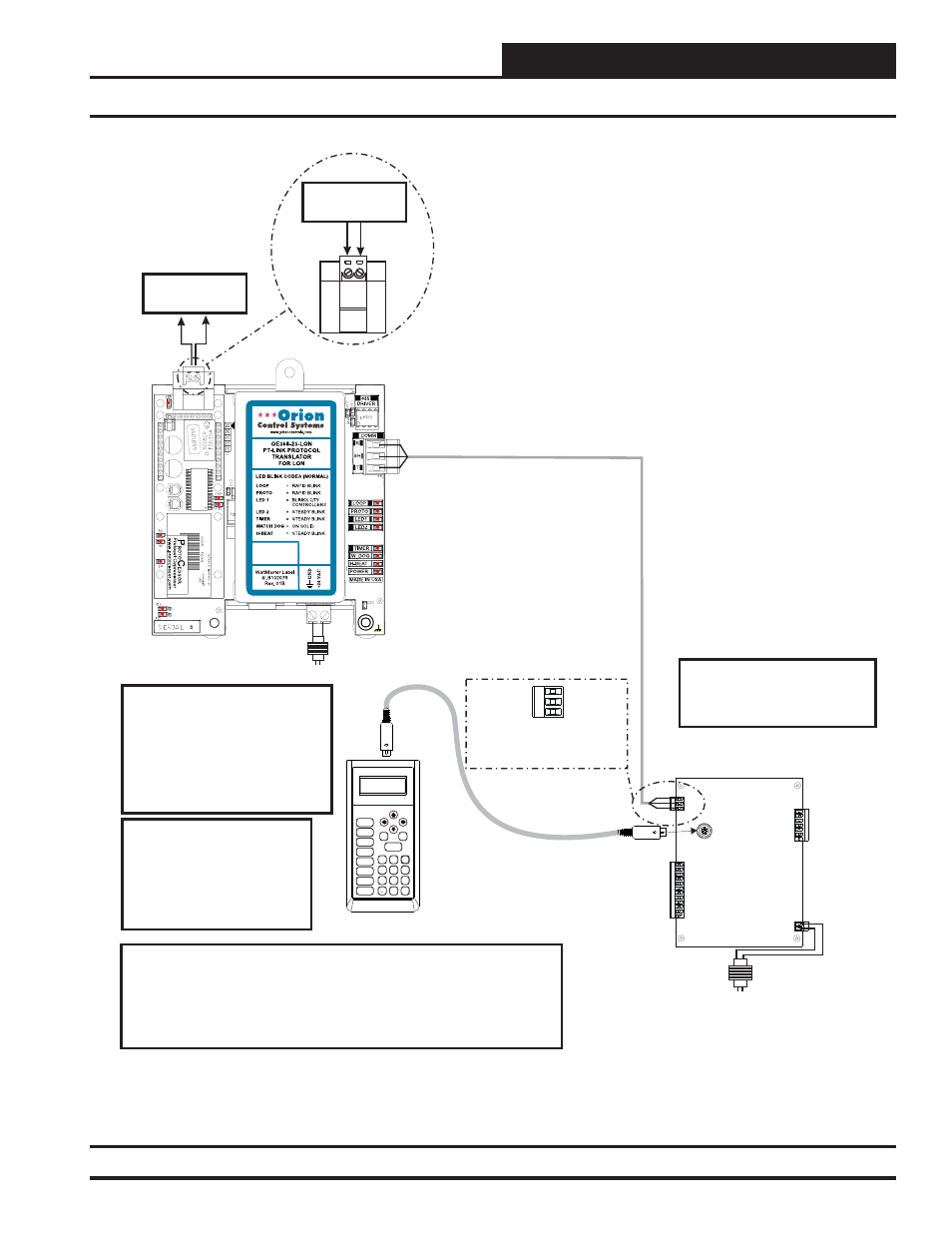
Connection and Wiring Information
Figure 2: PT-Link II LON
®
Interface
Wiring
Modular Service Tool
Mode
Selection
ENTER
CLEAR
ESC
PREV
NEXT
DOWN
UP
6
5
4
DEC
7
0
8
1
3
2
9
MINUS
-
STATUS
SETPOINTS
SCHEDULES
CONFIGURATION
ALARMS
ON
OVERRIDES
BALANCE - TEST
LON Connection
To LON Network
®
®
LON Connection
To LON Network
®
®
Line Voltage
24 VAC
(8 VA)
Controller
SHLD
T
R
Typical Terminal Blocks. All
Wiring To Be T To T, SHLD
(G) To SHLD (G) & R To R
Note: All Programming Of
Controllers Must Be Done
Using The Modular Service
Tool. The Modular System
Manager Should Not Be Used
On A System That Has A PT-
Link Installed.
Caution: The LON Network
Communication Terminal Block
Must Be Disconnected Before
Connecting The Modular Service
Tool. After Programming The
Controller, Disconnect The Service
Tool and Then Reconnect The
Communication Terminal Block.
®
Wiring Notes:
1.) All wiring to be in accordance with local and national electrical codes
and specifications.
2.) All communication wiring to be 18 gauge minimum, 2 conductor twisted
pair with shield. Use Belden #82760 or equivalent.
Line Voltage
24 VAC
(10 VA)
Controller’s Address
Cannot Be Higher Than 16.
Revised 8/31/11