Appendix g - vcm lon parameters, Pt-link ii lon, Technical guide – Orion System PT-Link II LON User Manual
Page 54: Pt-link ii interface 54, Snvts for the vcm controller
PT-Link II LON
®
Technical Guide
PT-Link II Interface
54
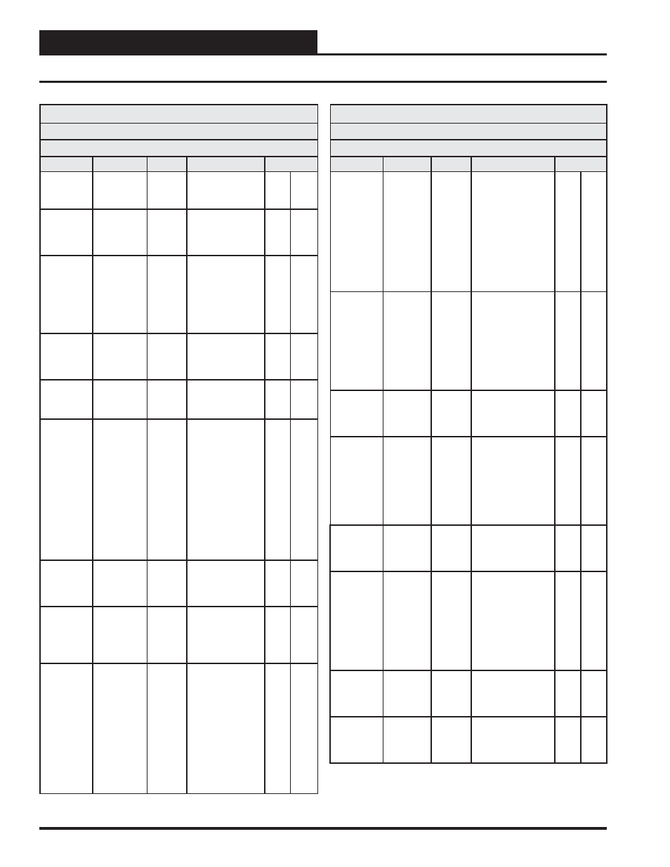
Appendix G - VCM LON Parameters
SNVTs for the VCM Controller
Binary Output SNVTs are SNVT_lev_disc
All other SNVTs are SNVT_count_inc_f
Parameter
Name
Object
Description
Limits
Return
Damper
Position
RaDmp
Analog
Output
Current position of
the return damper
signal.
Outdoor Air
Dewpoint
OaDwpt
Analog
Output
Current
calculated outdoor
air dewpoint added
on version 1.09.
Current
Supply Air
Setpoint
SaTpStM
Analog
Output
Current SAT
Cooling or Heating
setpoint if there
is no reset source;
Current calculated
SAT setpoint with
Reset Source.
Coil
Temperature
CoilTp
Analog
Output
Current coil
temperature
reading added on
version 1.09.
Preheater
Setpoint
PreHtSp
Analog
Input
Low Outside Air
Ambient Protection
Setpoint
0
100
CO
2
Setpoint
CO2St
Analog
Input
When the CO
2
level rises above
the CO
2
Protection
Limit Max Level,
the Economizer’s
Minimum Position
will begin to reset
open proportionally
between the CO
2
Protection Limit
Max Level Set-
point and the Reset
Range Setpoint.
0
3000
Static
Pressure
Setpoint
DuctPrSt
Analog
Input
This is the target
duct pressure to be
maintained by the
VFD blower signal.
0.01
3
Minimum
Outside Air
Setpoint
MinEcoSt
Analog
Input
This is the
minimum position
of the economizer
in the occupied
modes.
1
100
Occupied/
Mode
Enable
Cooling
Setpoint
OcpClSt
Analog
Input
If the control
temperature rises
one degree above
this setpoint,
the control will
activate the cooling
demand. If the
control temperature
is the Supply Air
Sensor, then the
cooling demand is
always active.
0
99
SNVTs for the VCM Controller
Binary Output SNVTs are SNVT_lev_disc
All other SNVTs are SNVT_count_inc_f
Parameter
Name
Object
Description
Limits
Occupied/
Mode
Enable
Heating
Setpoint
OcpHtSt
Analog
Input
If the control tem-
perature drops one
degree below
this setpoint,
the control will
activate the heating
demand. If the
control temperature
is the Supply Air
Sensor, then there is
no heating demand.
0
99
Outdoor
Air Sensor
Offset
OaTpOst
Analog
Input
If the Outdoor
Temperature Sensor
is reading incor-
rectly, you can use
this option to
enter an offset
temperature to adjust
the Sensor’s Tem-
perature.
-100
100
Relief
Pressure
Setpoint
RfPrSt
Analog
Input
This is the target
building pressure to
be maintained by the
VFD Relief signal.
-0.2
0.2
Return
Air Sensor
Offset
RaTpOst
Analog
Input
If the Return Tem-
perature Sensor is
reading incorrectly,
you can use this
option to enter an
offset temperature to
adjust the Sensor’s
Temperature.
-100
100
Schedule
Force
SchdFrc
Analog
Input
0 = Auto
Unoccupied Mode
1 = Forced On
2 = Forced Off
0
2
Space
Sensor
Offset
SpcTpOst
Analog
Input
If the Space
Temperature
Sensor is reading
incorrectly, you can
use this option to
enter an offset
temperature to
adjust the Sensor’s
Temperature.
-100
100
SAT/Reset
Source
Cooling
Setpoint
SaClSt
Analog
Input
Supply Air setpoint
or Reset Source
target temperature in
Cooling Mode.
40
80
SAT/Reset
Source
Heating
Setpoint
SaHtSt
Analog
Input
Supply Air setpoint
or Reset Source
target temperature in
Heating Mode.
40
200