Appendix e - vcm-x lon parameters, Pt-link ii interface, Pt-link ii lon – Orion System PT-Link II LON User Manual
Page 45: Technical guide 45
PT-Link II Interface
PT-Link II LON
®
Technical Guide
45
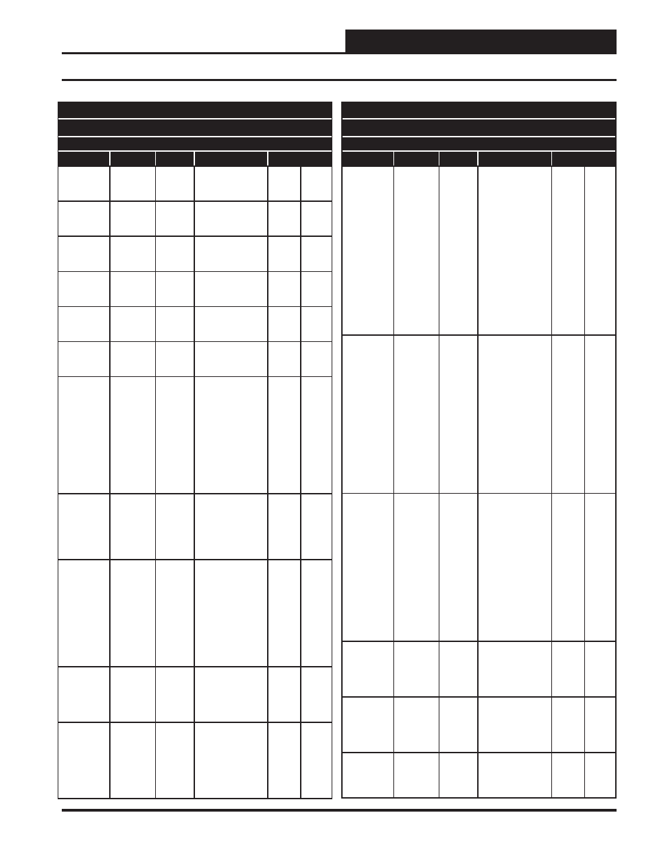
Appendix E - VCM-X LON Parameters
SNVTs for the VCM-X Controller
Binary Output SNVTs are SNVT_lev_disc
all other SNVTs are SNVT_count_inc_f
Parameter
Name
Object
Description
Limits
Supply Air
Cool High
Reset
SaClRt
Analog
Input
High Supply Air
Cooling Reset
Limit
40
150
Supply Air
Heat High
Reset
SaHtRt
Analog
Input
High Supply Air
Heating Reset
Limit
40
150
Cooling
Low Reset
Source
ClLoRt
Analog
Input
Low Cool Reset
Source Setpoint
1
150
Cooling
High Reset
Source
ClHiRt
Analog
Input
High Cool Reset
Source Setpoint
1
150
Heating
Low Reset
Source
HtLoRt
Analog
Input
Low Heat Reset
Source Setpoint
1
150
Heating
High Reset
Source
HtHiRt
Analog
Input
High Heat Reset
Source Setpoint
1
150
Warm Up
Setpoint
WmupSt
Analog
Input
In a VAV
application, upon
entering the
occupied mode,
the Warm-up
Demand will be
activated if the
return air tem-
perature falls one
degree below this
setpoint.
Wet Bulb
Setpoint
WtblSt
Analog
Input
The economizer is
enabled if the
outdoor tempera-
ture or wetbulb
falls below this
setpoint.
0
80
Coil
Temperature
Setpoint
CoilTpSt
Analog
Input
This is the coil
suction tempera-
ture target during
dehumidifi cation
mode. Produces
dewpoint in the
supply air
approximately
10°F above this
setpoint.
35
70
Relief
Pressure
Setpoint
RfPrSt
Analog
Input
This is the target
building pressure
to be maintained
by the VFD Relief
signal.
-0.2
0.2
Indoor
Humidity
Setpoint
InRhSt
Analog
Input
If the indoor
humidity rises
above this set-
point, the unit will
activate the
Dehumidifi cation
Demand.
0
100
SNVTs for the VCM-X Controller
Binary Output SNVTs are SNVT_lev_disc
all other SNVTs are SNVT_count_inc_f
Parameter
Name
Object
Description
Limits
Unoccupied
Cooling
Offset
UnClOst
Analog
Input
During the
Unoccupied Mode
of Operation, this
Setpoint spreads
the Occupied
Cooling Setpoint
out by a user
adjustable amount.
If you do not want
Cooling to operate
during the
Unoccupied
Mode, use the
default setting
of 30°F for these
setpoints.
0
30
Unoccupied
Heating
Offset
UnHtOst
Analog
Input
During the
Unoccupied Mode
of Operation, this
Setpoint spreads
the Occupied
Heating Setpoint
out by a user
adjustable amount.
If you do not want
Heating to operate
during the Unoc-
cupied Mode, use
the default setting
of 30°F for these
setpoints.
0
30
CO
2
Setpoint
CO2St
Analog
Input
When the CO
2
level rises above
the CO
2
Protection
Limit Max Level,
the Economizer’s
Minimum Position
will begin to reset
open proportion-
ally between the
CO
2
Protection
Limit Max Level
Setpoint and the
Reset Range
Setpoint.
0
3000
Minimum
Outside Air
Setpoint
MinEcoSt
Analog
Input
This is the
minimum position
of the economizer
in the occupied
modes.
1
100
Static
Pressure
Setpoint
DuctPrSt
Analog
Input
This is the target
duct pressure to
be maintained by
the VFD blower
signal.
0.01
3
Preheater
Setpoint
PreHtSp
Analog
Input
Low Outside Air
Ambient
Protection
Setpoint
0
100
Revised 2/12/14