Appendix c - vcb-x lon parameters, Pt-link ii interface, Pt-link ii lon – Orion System PT-Link II LON User Manual
Page 27: Technical guide 27
PT-Link II Interface
PT-Link II LON
®
Technical Guide
27
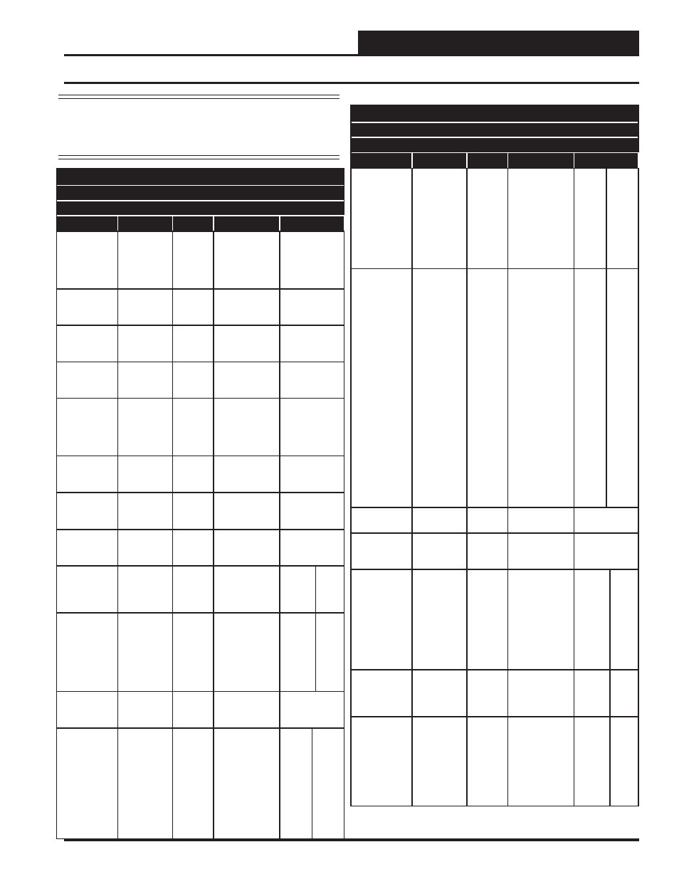
Appendix C - VCB-X LON Parameters
SNVTs for the VCB-X Controller
Binary Output SNVTs are SNVT_lev_disc
all other SNVTs are SNVT_count_inc_f
Parameter
Name
Object
Description
Limits
Bad or
Missing 12
Relay
Expansion
Board.
Mis12Rly
Binary
Output
The 12 Relay
Expansion
Board is con-
fi gured but not
detected.
Alarm
Group 1
AlmGrp1
Analog
Output
See Alarm
Group Bits on
page 38.
Alarm
Group 2
AlmGrp2
Analog
Output
See Alarm
Group Bits on
page 38.
Alarm
Group 3
AlmGrp3
Analog
Output
See Alarm
Group Bits on
page 38.
Alarm Status
AlmSts
Analog
Output
Indicates that
there is an
alarm.
0 = Off
1 = On
See Alarm
Group Bits on
page 38.
Application
Software
Version
AppVer
Analog
Output
Current version
of the software
in the unit.
Unit Mode
UnitMode
Analog
Output
See Unit Mode
Bits on page
38.
Building
Pressure
BuildPr
Analog
Output
Current value
of the building
pressure sensor.
Building
Pressure
Setpoint
RfPrSt
Analog
Input
Current
Building
Pressure
Setpoint.
-.20
.20
Building
Pressure
Control
Deadband
RfPrDb
Analog
Input
Value above
and below the
Building
Pressure
Setpoint where
no control
change occurs.
.01
0.1
CO
2
CO2
Analog
Output
Current CO
2
Level.
CO
2
Sensor
Calibration
Deadband
Offset
CO2Ost
Analog
Input
If the CO
2
Sensor is
reading
incorrectly, you
can use this
option to enter
an offset value
to adjust the
Sensor’s CO
2
reading.
-500
ppm
500
ppm
SNVTs for the VCB-X Controller
Binary Output SNVTs are SNVT_lev_disc
all other SNVTs are SNVT_count_inc_f
Parameter
Name
Object
Description
Limits
CO
2
Minimum
Setpoint
CO2MinLv
Analog
Input
This is the
threshold CO
2
level at which
the Economizer
Min Damper
Position
Setpoint will
begin to be
reset higher.
0
2000
CO
2
Maximum
Setpoint
CO2
MaxLv
Analog
Input
This is the CO
2
level at which
the Economizer
Min Damper
Position will
be reset to the
Economizer
Max Position
in High CO
2
.
In between the
Min and Max
CO
2
levels the
Economizer
Min Damper
Position will be
proportionally
reset between
the confi gured
Min Damper
Position and the
Max Position in
High CO
2
.
0
2000
Bad CO
2
Sensor
CO2Alm
Binary
Output
Failure of the
CO
2
Sensor.
Coil
Temperature
CoilTp
Analog
Output
Current coil
temperature
reading.
Coil
Temperature
Offset
ColTpOft
Analog
Input
If the Coil
Temperature
Sensor is
reading
incorrectly, use
this offset to
adjust the
Sensor’s
Temperature.
-100
100
Bad Coil Pres-
sure
Sensor
ColPrAlm
Binary
Output
Failure of the
Coil Pressure
Sensor. Will
shut unit down.
Coil Tempera-
ture Setpoint
CoilTpSt
Analog
Output
This is the
current
calculated Coil
Suction
Temperature
target during
Dehumidifi ca-
tion Mode.
NOTE:
When using Celsius scaling, all temperature values will
need to be divided by 10 by the BMS to properly read the
status and setpoint values, e.g., a value of 200º C needs
to be divided by 10 for an actual value of 20º C.