Component & system wiring 10 – Orion System VCM Component User Manual
Page 10
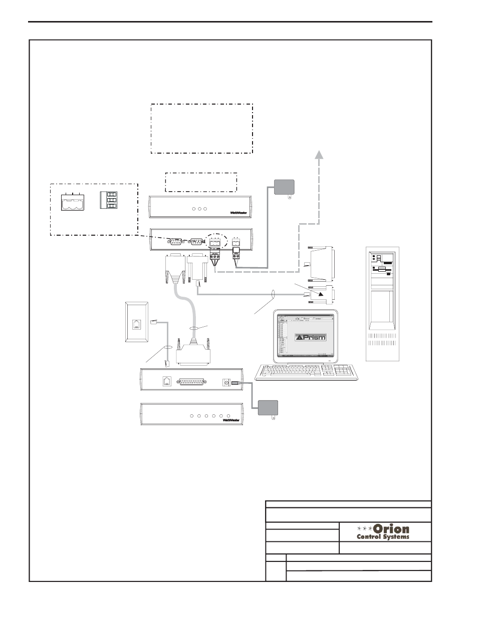
Component & System Wiring
10
Notes:
1.) All wiring to be in accordance with local and national electrical codes
and specifications.
FILENAME
DATE:
B. Crews
DESCRIPTION:
PAGE
DRAWN BY:
Wiring & Connection Diagram
JOB NAME
06/20/03
O-System-Interconnected.CDR
Interconnected System
2 of 3
Connect To HVAC Unit Controller
See Page 1 Of This Drawing For Wiring
9 Pin
Female
End
Telephone
Cable
Assembly
9 Pin
Female
Connector
9 Pin
Female
Connector
Molded
Cable Assembly
25 Pin
Male End
25 Pin
Female
Connector
(If Reqd)
Connect To Computer
Serial Port
Personal Computer
(By Others)
Dedicated Telephone
Outlet
(By Others)
Back View of CommLink
Back View of Remote Link
Note: CommLink Is Only Required If
Alarm Callout, Remote Computer
Connection Or Direct Computer
Connection To System Is Desired.
Remote Link Is Only Required If
Alarm Callout Or Remote Computer
Connection Is Required.
Front View of Remote Link
C
L
II
omm ink
LOOP
24V
T G R
GND
REMOTE LINK
(DTE)
COMPUTER
(DCE)
485
LOOP
STATUS
POW
ER
COMP
RLINK
SERIAL #
C
O
N
T
R
O
L
S
R
L
emote
ink
SIG
TELCO
LINE
TELCO
LINE
SERIAL DATA
DET
RDY
SND
REC
PWR
SERIAL #
C
O
N
T
R
O
L
S
POWER
9VDC @
500mA
8 Conductor
Modular Cable
Assembly
110 VAC To
9 VDC
Power Pack
110 VAC To
24 VAC
Power Pack
Remote Link
(Optional)
SHLD
T
R
Typical Terminal Blocks. All
Wiring To Be T To T, SHLD (G)
To SHLD (G) & R To R
T G R
485
LOOP
Front View of CommLink
CommLink
Note: Set CommLink
Internal Switch To “Single”
Optional Computer Connection Diagram
Using Remote Link For Remote Connection
Interconnected - Computer Connection With Remote Link