Vcm controller wiring, Component & system wiring 32, Vcm controller main board wiring – Orion System VCM Component User Manual
Page 32: All comm loop wiring is straight thru, T to t, r to r & shld to shld, Ovcm-mainwire-1a.cdr, Line voltage
Component & System Wiring
32
VCM Controller Wiring
FILENAME
DATE:
B. Crews
DESCRIPTION:
PAGE
DRAWN BY:
JOB NAME
OVCM-MainWire-1A.CDR
1 of 1
02/28/06
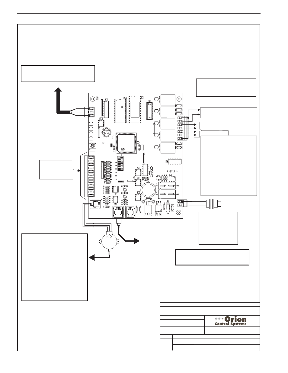
Line Voltage
All Comm Loop Wiring Is
Straight Thru
24VAC
GND
Local Loop
RS-485
9600 Baud
See Individual
Component Wiring
Diagrams For Detailed
Wiring Of Analog Inputs
And Outputs
For Stand Alone Applications,
Connect To System Manager. For Network
Applications Connect To Next Controller And/Or
MiniLink PD On Local Loop.
G - Fan ON/OFF Only
R - 24VAC
Relay Output Dry Contacts
R2 Thru R5 May Be User Configured
For The Following:
1 - Heating Stages
2 - Cooling Stages
3 - Warm-up Mode Command (VAV Boxes)
4 - Reversing Valve (Air To Air Heat Pumps)
5 - Reheat Control (Dehumidification)
6 - Exhaust Fan Interlock
7 - Preheater For Low Ambient Protection
8 - Alarm
9 - Override
10 - Occupied
11 - OA Damper
Note: A Total Of 20 Relays Are Available By
Adding Relay Expansion Boards. All Expansion
Board Relay Outputs Are User Configurable As
Listed Above.
OE271
Static Pressure
Transducer
Splice If Req’d
Connect To
Expansion Board
Base (When Used)
RL
Y1
D1
D2
D3
D4
D5
RAM
C3
C2
U6
PHILIPS
CX6
C1
CX2
U2
PAL
CX4
U4
TUC-5R PLUS
YS101816 REV. 2
V1
V2
V3
V5
V4
TB2
4
NETWORK
TOKEN
16
32
8
SW1
ADD
2
1
ADDRESS
V6
POWER
GND
24VAC
L1
D16
R6
C9
SC1
R1
1
U1
1
MC34064A
D13
C16
9936
VR2
TB4
R27
C13
R10
VR1
C19
C18
NE5090NPB3192
0PS
U8
CX8
U9
X1
R7
D10
R13
D12
C7
CX10
U10
CX12
U12
U14
CX14
PJ3
PJ2
PJ1
EXPANSION
PRESSURE
SENSOR
C17
D15
R26
C20
R25
R24
R22
U15
CX13
U13
C15
R19
R15
C14
D18
D17
PU1
PU2
PU3
PU4
PU5
PU7
D6
D7
D8
D9
D11
D14
C12
C10
0-5
VDC
0-1
VDC
JP1
C1
1
X2
GND
TB3
INPUTS
GND
GND
+VDC
AIN1
AIN2
AIN3
AIN4
AIN5
AOUT1
AOUT2
AIN7
RN4
1
RN5
RS-485
CX5
U5
R
TB1
SHLD
T
COMM
COMM
RN3
1
RN1
U1
CX1
1
LD6
COMM
PWR
LD7
LED1
LED2
LD9
LD8
R1
U7
RV1
VREF ADJ
R28
+VREF
5.11V
TEST POINT
EWDOG
D19
RN2
1
COM1-3
COM4-5
R5
R4
R3
R2
R1
RL
Y2
RL
Y3
RL
Y4
RL
Y5
CX15
(1 MEG)
HH
P1
C21
CX3
EPROM
U3
Warning:
24 VAC Must Be Connected So That All Ground
Wires Remain Common. Failure To Do So Will
Result In Damage To The Controllers.
T to T, R to R & SHLD to SHLD
Size Transformer For
Correct Total Load.
VCM Controller = 8 VA
Power Consumption. If
Economizer Option Is Used
The Economizer Actuator
VA load Must Also Be
Considered When Sizing
The Transformer.
OE331-21-VCM
VCM Controller Board
Note:
All Relay Outputs Are Normally Open
And Rated For 24 VAC Power Only.
2 Amp Maximum Load.
VCM Controller
Main Board Wiring
Notes:
1.) Connect FRP Tubing To The High Pressure
Port (Bottom Tube) Of The Staic Pressure
Transducer And Route The Tubing To The
Static Pressure Pickup Probe Location. Leave
The Port Marked “LO” Open To Atmosphere.
2.) The Static Pressure Pickup Probe Should
Ideally Be Mounted With The Probe Pointing
At A 90 Degree Angle To The Supply Air Flow
Direction. It Should Be Located In A Straight
Section Of The Supply Air Duct At A Distance
From The Unit Discharge That Is Approximately
Equal To 2/3 The Length Of The Longest
Supply Air Duct Run. Also Ideally The Probe
Should Be Located Not Less Than 3 Duct
Diameters Downstream And 2 Duct Diameters
Upstream Of Any Elbow Or Takeoff In The
Ductwork.