System manager modular cable connections, Component & system wiring 58, System manager wiring using modular cables – Orion System VCM Component User Manual
Page 58: Philipsphilips, Component wiring diagram, Oe392 orion modular system manager, Job name, 1 of 3, O-systemmgrwire1a.cdr
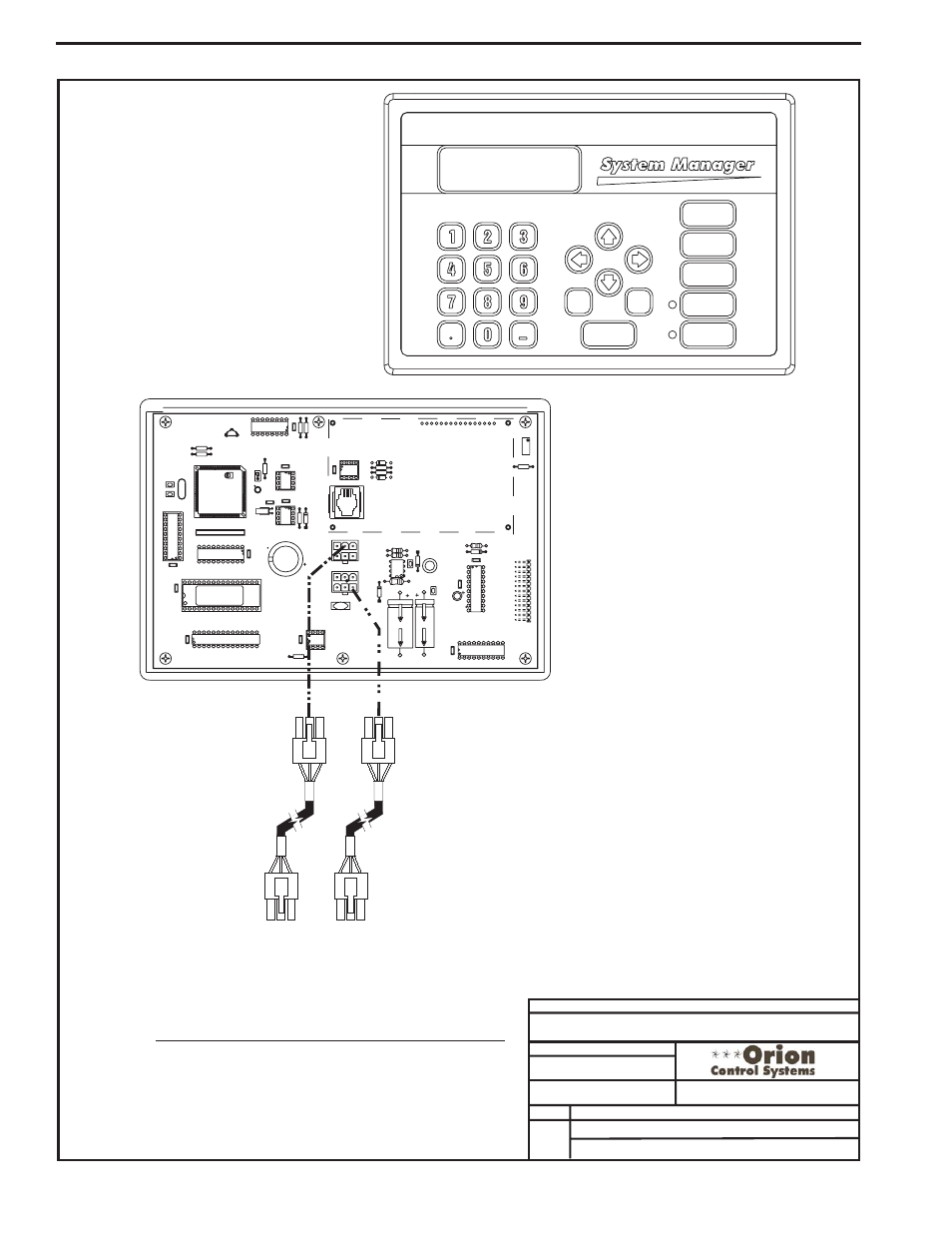
Component & System Wiring
58
Notes:
1.) All wiring to be in accordance with local and national electrical codes
and specifications.
See Page 2 and 3 of this Diagram for Alternate Hard Wiring Information
2.) All modular power/comm cables are to be WattMaster part number
PCC-xx or PCCE-xx cables.
Power/Comm Cables To
Power/Comm
Or VAV/Zone Controllers On
Local Loop. See Page 2 Of This
Drawing For Wiring With A Stand
Alone Controller.
Distribution Board,
FILENAME
DATE:
B. Crews
B. Light
DESCRIPTION:
PAGE
DRAWN BY:
Component Wiring Diagram
JOB NAME
O-SYSTEMMGRWIRE1A.CDR
OE392 Orion Modular System Manager
1 of 3
PREV
DEC
MINUS
UP
NEXT
DOWN
ENTER
ESC
CLEAR
ALARMS
OVERRIDES
SCHEDULES
SETPOINTS
STATUS
Modular System Manager
Front Cover
Modular System Manager
Back of Front Cover
P1
P2
VAR1
U13
RS-485P
COMM
R14
U6
V62C518256L-70P
CX11
CX12
U12
U11
CX7
PA
L
EPROM
RAM
CX13
75176
U8
74HC573
CX8
RN1
SC1
YS101830PREV.
YS101830PREV.
2PMODULARPSYSTEM
2PMODULARPSYSTEM
MANAGER
PCB80C552-5-16WPP442860=2/5PCB80C552-5-16WPP442860=2/5
PDfD9722V7
Y
PDfD9722V7
Y
C2
U7
X1
C1
R1
R4
EWDOG
PHILIPS
X2
C3
PHILIPSPHILIPS
U3
CX5
R3
R9
8583
CX6
D3
U4
24C128
CX4
74HC259
U1
U2
CX2
R3
R2
U14
C8
CX9
C7
470uF50v
1000uF10v
470uF50v
1000uF10v
R12
R11
COMM
OUT
COMM
OUT
COMM
IN
COMM
IN
D6
C4
R13
MC34064AMC34064A
U9
9936
D5
L1
U10
74HC540
CX14
C6
P3
CX10
C5
74HC923
R10
D4
CX3
82B715
PJ1
D2
R6
R5
D1
U3
DSPY1
R7
RV1
02/11/04
System Manager Wiring Using Modular Cables
System Manager Modular Cable Connections