Return air humidity sensor wiring, Component & system wiring 43, Vcm controller wiring detail – Orion System VCM Component User Manual
Page 43
Component & System Wiring
43
FILENAME
DATE:
B. Crews
DESCRIPTION:
PAGE
DRAWN BY:
JOB NAME
OVCM-RA-HumSensorWr-1A.CDR
1 of 1
03/06/06
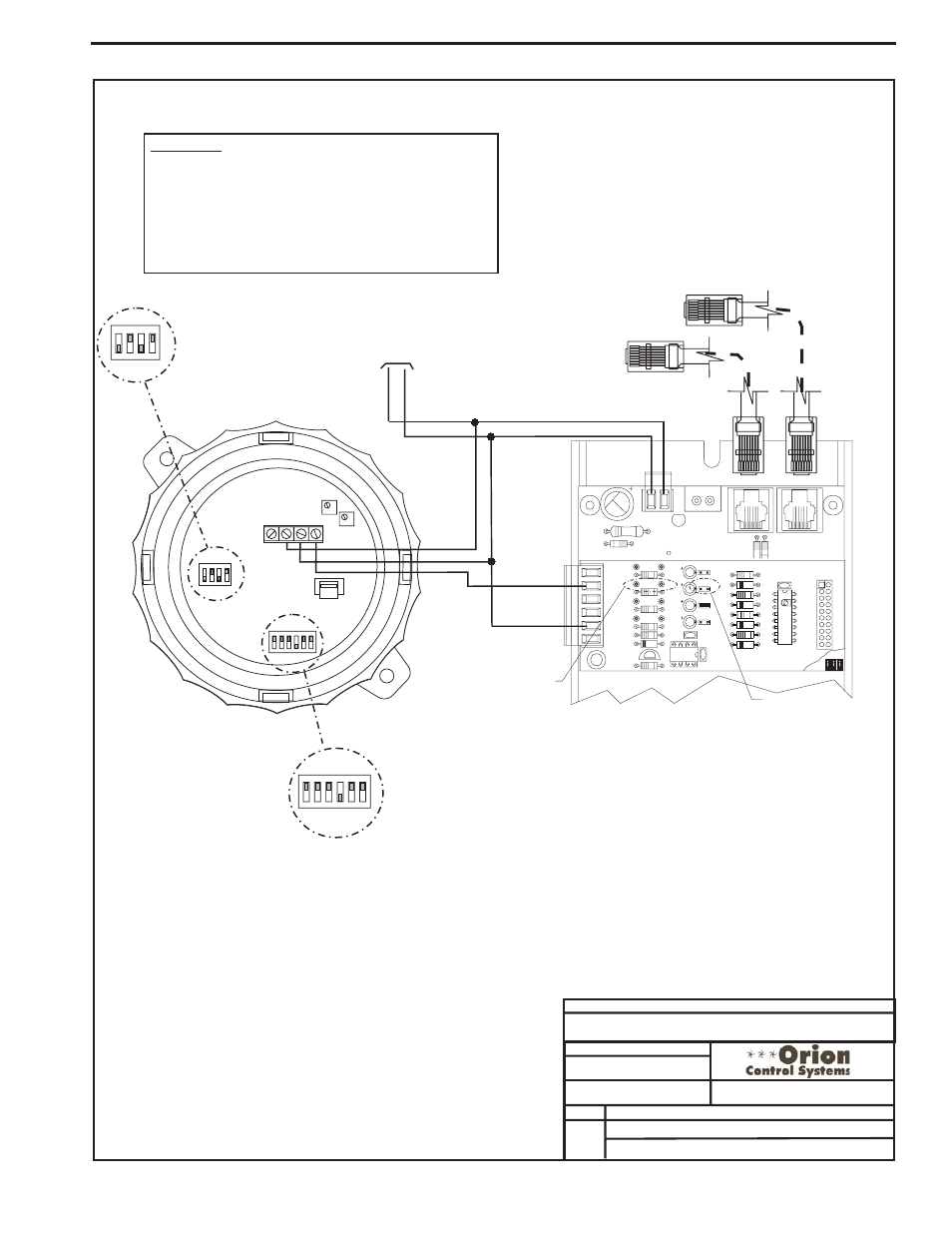
VCM Controller Wiring Detail
Return Air Humidity Sensor
Jumpers Must Be Set
as Shown For Correct
O-5 VDC Operation
1 & 3 Are Off
2 & 4 Are On
Jumpers Must Be
Set as Shown For
Normal
1, 2, 4, 5 & 6 Are
Off
3 Is On
Operation Of
Sensor
4
4
4
5
5
6
6
ON
ON
ON
3
3
3
2
2
2
1
1
1
4
ON
3
2
1
24
V
A
C
GND
10 VA Minimum Power Required For
Each 2 Slot Expansion Base Board.
20 VA Minimum Power Required For
Each 4 Slot Expansion Base Board
R20
C8
TB2
D3
PWR LD1
24V
AC-IN
GND
GND
TB1
PJ2
+24VDC-OUT
R17
PJ1
R15
Connect To VCM Controller
Connect To Next
Expansion Base Board
(When Used)
OE354
-
4
Analog
Input
1
Analog
Output
Board
GND
AIN2
0-5 VDC Input
JO3
JO4
JO2
JO1
CX2
R10
AOUT1
AIN4
TB1
GND
AIN2
AIN3
AIN1
PU4
U2
D5
Q1
R8
R9
LM358
C5
C1
R7
R6
R5
PU3
C4
C3
C2
PU2
PU1
4 ANALOG IN MOD. I/O BD.
R3
YS101784
D4
R4
D3
D1
D2
R2
R1
CX1
U1
P1
Pullup Resistor PU2 Must
Be Removed As Shown
Jumper J02 Must
Be Removed As Shown
OE352 or OE353 Expansion Base Board
OE265-14
RA Humidity Sensor
WARNING!!
Observe Polarity! All boards must be wired with GND-to-
GND and 24VAC-to-24VAC. Failure to observe polarity will
result in damage to one or more of the boards. Expansion
Boards must be wired in such a way that power to both the
expansion boards and the controller are always powered
together. Loss of power to the expansion board will cause
the controller to become inoperative until power is restored
to the expansion board.
4-20
mA
Zero
Span
V
A
Co
rD
C
GND
0-5V
or
0-10V
Return Air Humidity Sensor Wiring