Interconnected system wiring, Typical interconnected system, Component & system wiring 9 – Orion System VCM Component User Manual
Page 9: Wiring & connection diagram, Interconnected system, 1 of 3, Line voltage hvac unit controller 24 vac (8 va)
Component & System Wiring
9
Notes:
1.) All wiring to be in accordance with local and national electrical codes
and specifications.
FILENAME
DATE:
B. Crews
DESCRIPTION:
PAGE
DRAWN BY:
Wiring & Connection Diagram
JOB NAME
06/20/03
O-System-Interconnected.CDR
Interconnected System
1 of 3
TB1
Connect To Modular
I/O Connectors
Located On Back
Of The System Manager
ENTER
CLEAR
ESC
PREV
NEXT
DOWN
UP
6
5
4
DEC
7
0
8
1
3
2
9
MINUS
-
STATUS
SETPOINTS
SCHEDULES
ALARMS
OVERRIDES
WHITE (T)
DRAIN WIRE (SHLD)
BLACK (R)
RED (24 VAC)
Line Voltage
Modular Service Tool
Modular System Manager
24 VAC
(6 VA)
CLEAR (GND)
GREEN (GND)
Mode
Selection
ENTER
CLEAR
ESC
PREV
NEXT
DOWN
UP
6
5
4
DEC
7
0
8
1
3
2
9
MINUS
-
STATUS
SETPOINTS
SCHEDULES
CONFIGURATION
ALARMS
ON
OVERRIDES
BALANCE - TEST
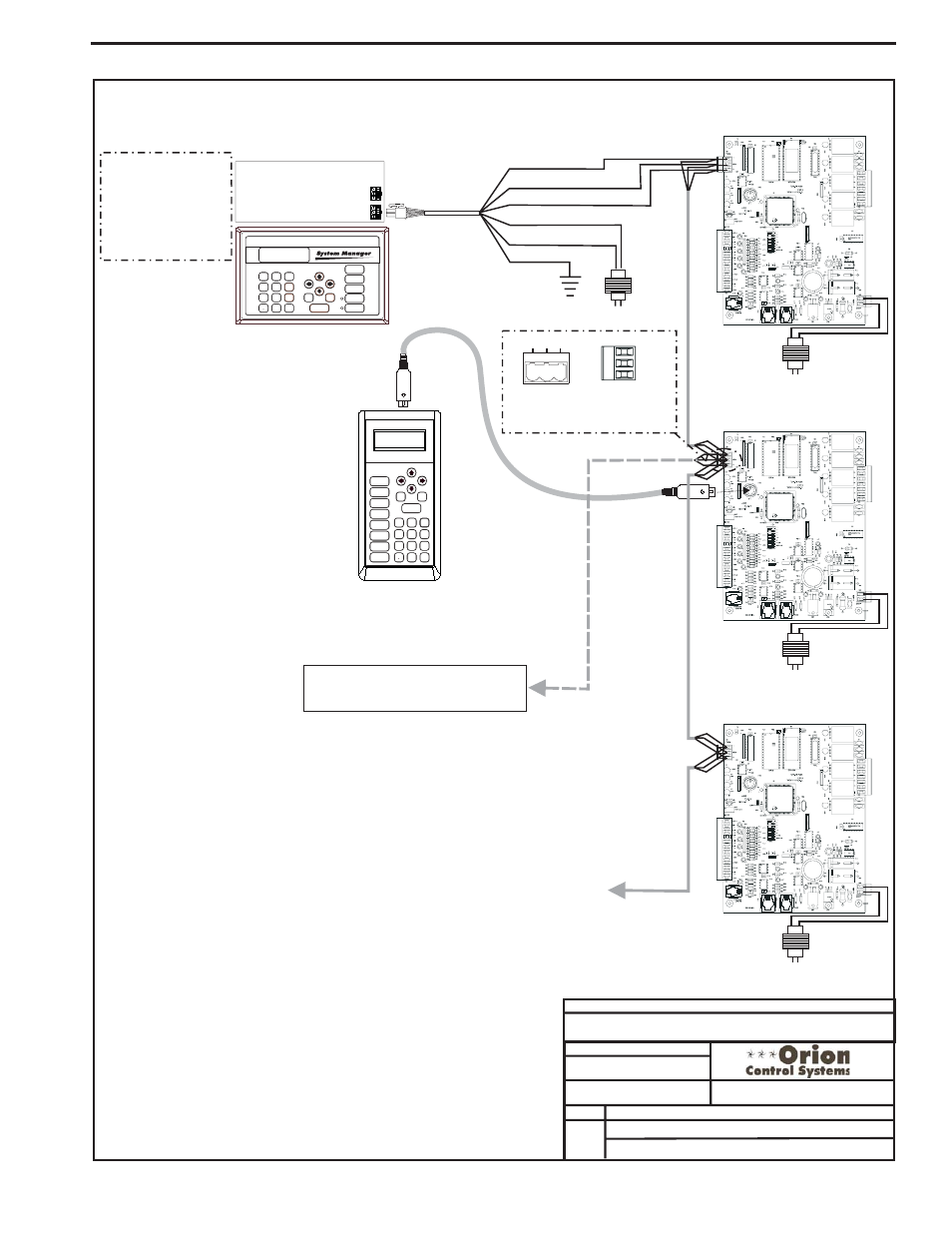
To Next HVAC Unit
Controller On Loop
Up To 60 Controllers
Can Be Interconnected
Note: Either A Modular
System Manager, A
Modular Service Tool
Or A PC With Prism
Software Installed Can
Be Used To Program
And Configure The
Orion System.
Line Voltage
HVAC Unit Controller
24 VAC
(8 VA)
(1 MEG)
Line Voltage
HVAC Unit Controller
24 VAC
(8 VA)
(1 MEG)
Line Voltage
HVAC Unit Controller
24 VAC
(8 VA)
(1 MEG)
Connect To Optional
CommLink (When Used)
For Optional CommLink, Remote Link
And Computer Connections, See Page 2
Of This Drawing.
SHLD
T
R
Typical Terminal Blocks. All
Wiring To Be T To T, SHLD (G)
To SHLD (G) & R To R
T G R
485
LOOP
Typical Interconnected System
Interconnected System Wiring