Component & system wiring 65, Warning, Caution – Orion System VCM Component User Manual
Page 65
Component & System Wiring
65
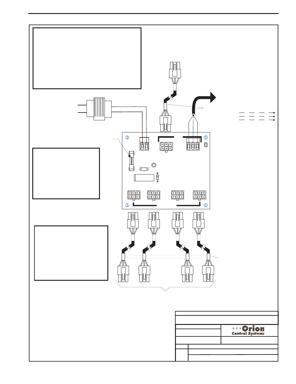
Power/Comm Board Wiring - When Used For Local Loop Devices
Notes:
1.) All wiring to be in accordance with local and national electrical codes
and specifications.
2.) All modular power/comm cables are to be WattMaster part number
PCC-xx or PCCE-xx cables. All other communication wiring to be 2
conductor twisted pair with shield (Belden #82760 or equivalent).
Power/Comm Cable
Power/Comm Board,
System Manager, Or VAV/Zone Controller On Local Loop
If This Is The First Power/Comm Board On The Local Loop,
No Connection Is Required. See Note 2.
From Other
Power/Comm Cable To
Power/Comm
System Manager, Or VAV/Zone Controllers On Local Loop Only.
Other
Board(s),
Connect To VAV/CAV Controller
If This Is First Power/Comm Board
On Local Loop - Otherwise No
Connection Is Required. See Note 2.
FILENAME
DATE:
B. Crews
DESCRIPTION:
PAGE
DRAWN BY:
Component Wiring Diagram
JOB NAME
02/11/004
O-Pwr-CommWire1A.CDR
OE365-01 Orion Power/Comm Board
1 of 2
TB2
VA
C
F1
25
4A
24
SHLD
T
R
POWER
LD1
TB1
C1
POWER
&
COMM
DIST
.
B
OARD
YS101856
REV
.
0
P5
P4
P3
P1
D1
V1
R1
P2
COMMPIN
POWER&
COMM
OUT
Line Voltage
24VAC
R
SH
T
R
SH
T
R
SH
T
R
SH
T
All Comm Loop Wiring Is
Straight Thru
Local Loop RS-485
9600 Baud
Local Loop RS-485
9600 Baud
24VAC Transformer (By Others)
See System Configuration Installation &
Commissioning Section Of This Manual
For Detailed Sizing Information
4 Amp Slow Blow Fuse
WARNING!
DO NOT GROUND THE 24V TRANSFORMER
THAT IS TO BE USED WITH THE POWER/COMM
BOARDS. GROUNDING OF THE TRANSFORMER
WILL DAMAGE THE POWER/COMM BOARD
AND ALL BOARDS CONNECTED TO IT. A
SEPARATE TRANSFORMER MUST BE USED
FOR EACH POWER/COMM BOARD. NO
EXCEPTIONS. DO NOT CONNECT ANY OTHER
DEVICES TO THE TRANSFORMER USED FOR
THE POWER/COMM BOARD!
Note:
Diagram Shown Is For Wiring Of
Power/Comm Board When Used
For Connecting Local Loop Devices
Such As VAV/Zone Controllers,
System Manager(s) and Other
Power/Comm Boards . See Page 2
Of This Drawing For Wiring When
Power/Comm Board Is Used For
Connection Of MiniLink Polling
Devices On The Network Loop.
CAUTION!
No
Can Be
Connected To The Same
Power/Comm Board(s) That
Are Used To Supply Power
And Communications For
VAV/Zone Controllers And
System Manager On The
Local Loop.
MinLink PDs