Networked multiple loop system wiring, Component & system wiring 17, Gnd ain2 ain1 +5v tb2 – Orion System VCM Component User Manual
Page 17: Cx14 network driver rn3, Controls, Philips
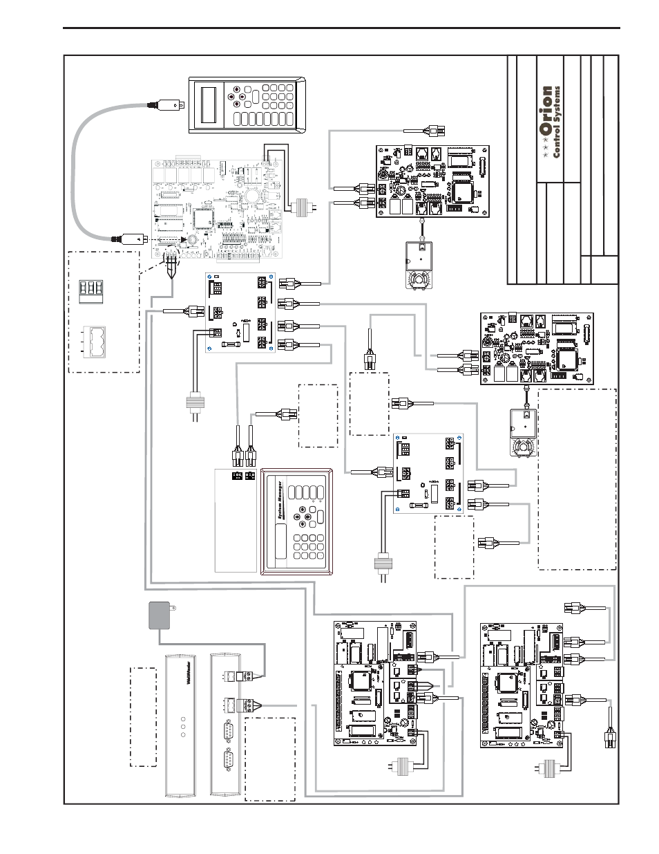
Component & System Wiring
17
EPROM
U3
U5
RAM
CX2
1
U2
R1
C3
U4
CX3
CX4
YS101818P552
PROCESSORPBOARD
CX5
C1
U1
R2
CX1
CX6
WDOG
U6
PHILI
PS
D1
P1
X1
C2
C4
0-10V
4-20mA
THERM
R27
R31
D4
GND
24VAC
TB1
D5
C1
1
U12
LED
2
POWER
V1
R25
R26
C7
CX15
CX13
PROC.
DRIVER
LOOP
DRIVER
LOCAL
LOOP
GND
AIN2
AIN1
+5V
TB2
P4
OFF=0-5V
AIN2
AIN1
0-10V
4-20mA
THERM
TB3
U15
LD5
LD6
U13
C8
LED
1
RV
1
R4
VREF
CX2
U1
1
YS101900PMINILINK
POLLING
DEVICE
REV
.
1
OFF
1
2
4
8
16
32
CX14
NETWORK
DRIVER
RN3
SHLD
SHLD
T
T
TB4
R
R
U14
NETWORK
LOOP
P5
ADD
P3
R24
LD4
C9
U10
RN2
SW1
R30
X2
R29
R28
C10
U6
CX6
CX1
U7
U1
X1
C3
C1
R3
CX7
EPROM
U3
U5
RAM
CX2
1
U2
R1
C3
U4
CX3
CX4
YS101818P552
PROCESSORPBOARD
CX5
C1
U1
R2
CX1
CX6
WDOG
U6
PHILIPS
D1
P1
X1
C2
C4
0-10V
4-20mA
THERM
R27
R31
D4
GND
24VAC
TB1
D5
C1
1
U12
LED
2
POWER
V1
R25
R26
C7
CX15
CX13
PROC.
DRIVER
LOOP
DRIVER
LOCAL
LOOP
GND
AIN2
AIN1
+5V
TB2
P4
OFF=0-5V
AIN2
AIN1
0-10V
4-20mA
THERM
TB3
U15
LD5
LD6
U13
C8
LED
1
RV
1
R4
VREF
CX2
U1
1
YS101900PMINILINK
POLLING
DEVICE
REV
.
1
OFF
1
2
4
8
16
32
CX14
NETWORK
DRIVER
RN3
SHLD
SHLD
T
T
TB4
R
R
U14
NETWORK
LOOP
P5
ADD
P3
R24
LD4
C9
U10
RN2
SW1
R30
X2
R29
R28
C10
U6
CX6
CX1
U7
U1
X1
C3
C1
R3
CX7
Network
Network
Local
Local
24
V
A
C
(6
V
A
)
24
V
A
C
(6
V
A
)
Back
V
iew
of
CommLink
Front
V
iew
of
CommLink
CL
II
omm
ink
LOOP
24V
T
G
R
GND
REMOTE
LINK
(DTE)
COMPUTER
(DCE)
485LOOP
ST
A
TUS
POWER
COMP
RLINK
SERIAL
#
CONTROLS
11
0
V
A
C
T
o
24
V
A
C
Power
Pack
CommLink
MiniLink
PD
Loop
1
MiniLink
PD
Loop
2
Note:
See
Page
2
O
f
This
D
rawing
For
Optional
Computer
And
Remote
L
ink
Connection
D
iagram.
Note:
Set
CommLink
Internal
Switch
T
o
“Multi”
Line
V
o
lt
age
24
V
A
C
(8
V
A
)
V
A
V/Zone
Controller
HV
AC
Unit
Controller
(1
MEG)
1
0
PHILIPS
Modular
Service
T
ool
Mode
Selection
ENTER
CLEAR
ESC
PREV
NEXT
DOWN
UP
6
5
4
DEC
7
0
8
13
2
9
MINUS
-
ST
A
T
US
SE
TPOINTS
SCHEDULES
CONFIGURA
TION
AL
ARMS
ON
OVERRIDES
BAL
A
NCE
-
TEST
Connect
T
o
Next
V
A
V
/Zone
Controller
On
Branch
Circuit
SHLD
T
R
T
ypical
T
e
rminal
Blocks.
All
W
iring
T
o
B
e
T
T
o
T
,
SHLD
(G)
T
o
SHLD
(G
)&RT
oR
T
G
R
485LOOP
FILENAME
DA
TE:
B.
Crews
DESCRIPTION:
P
AGE
DRA
WN
BY
:
JOB
NAME
1o
f3
T
ypical
Multiple
Loop
Netw
or
k
e
d
System
Power/Comm
Board
Line
V
o
lt
age
2
4
V
A
C-S
iz
e
T
ransformer
For
Required
V
A
Load
TB1
Connect
T
o
Modular
I/O
Connectors
Located
On
Back
Of
The
System
Manager
ENTER
CLEAR
ESC
PREV
NEXT
DOWN
UP
6
5
4
DEC
7
0
8
13
2
9
MINUS
-
ST
A
TUS
SE
TPOINTS
SCHEDULES
AL
ARMS
OVERRIDES
Modular
System
Manager
Note:
A
Modular
System
Manager
,
A
Modular
Service
T
ool
Or
A
P
C
W
ith
Prism
Sof
tware
Inst
alled
Can
Be
Used
T
o
Program
And
Configure
The
Orion
System.
TB2
VAC
F1
25
4A
24
SHLD
T
R
POWER
LD1
TB1
C1
POWER & COMM
DIST. BOARD
YS101856
REV. 0
P5
P4
P3
P1
D1
V1
R1
P2
COMMP
IN
POWER
&
C
OMM
OUT
Connect
T
o
Other
V
A
V
/Zone
Controllers
On
Loop
Connect
T
o
Other
V
A
V
/Zone
Controllers
On
Loop
Connect
T
o
Other
V
A
V
/Zone
Controllers
On
Loop
Power/Comm
Board
V
A
V/Zone
Controller
Line
V
o
lt
age
2
4
V
A
C-S
iz
e
T
ransformer
For
Required
V
A
Load
Note:
A
Maximum
Of
6
V
A
V
/Zone
Controllers
Can
Be
Connected
T
o
Each
Branch
Circuit.
A
tot
al
Of
16
Controllers
Are
A
llowed
Per
Power/Comm
Board.
Use
Additional
Power/Comm
Boards
For
Systems
That
Exceed
16
Controllers.
See
The
V
A
V
/Zone
Controller
W
iring
D
iagram
For
Power/Comm
Board
T
ransformer
Sizing
And
Circuit
Design
Information.
1
0
PHILIPS
TB2
VAC
F1
25
4A
24
SHLD
T
R
POWER
LD1
TB1
C1
POWER & COMM
DIST. BOARD
YS101856
REV. 0
P5
P4
P3
P1
D1
V1
R1
P2
COMMP
IN
POWER
&
COMM
OUT
Connect
T
o
Loop
2
Power/Comm
Board
Or
HV
AC
Unit
Controller
ConnectT
oLoop
3M
iniLinkP
D
Wiring
&
C
onnection
Diagram
O-Network-MultipleLoop1B.CDR
Networked
System
-
M
ultiple
Loop
10/30/03
Networked Multiple Loop System Wiring