Component & system wiring 64, 24 v a c class 2 t ransformer, Philips – Orion System VCM Component User Manual
Page 64
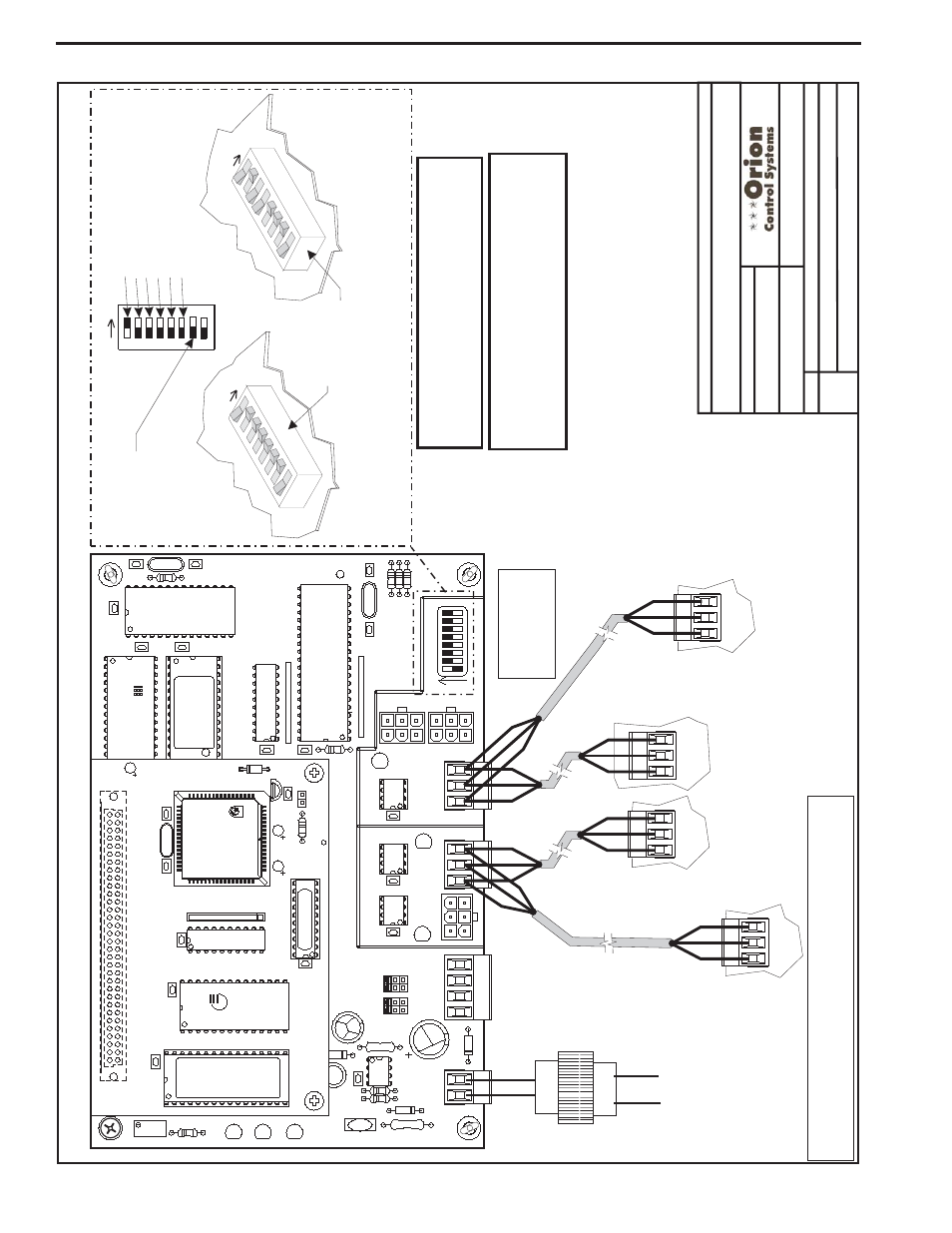
Component & System Wiring
64
Notes:
1.)
A
ll
Wiring
T
o
B
e
In
Accordance
With
Local
And
National
Electrical
Codes
And
S
pecifications.
2.)
A
ll
Modular
Power/Comm
Cables
Are
T
o
B
e
W
attMaster
Part
Number
PCC-XX
Or
PCCE-XX
Cables.
3)
Connection
T
o
The
Power/Comm
Board
And/Or
Other
MiniLink
PDs
Can
Be
Made
By
Using
The
Local
Loop
Modular
Connector
As
Shown
On
Page
1
O
r
B
y
Using
2
Conductor
With
Shield
Communication
W
ires
A
s
Shown
On
Page
2.
Connections
T
o
The
HV
AC
Unit
Controller
Must
Be
Made
By
Using
2
Conductor
With
Shield
Communication
W
ires
Only
.
Component
Wiring
Diagram
O-MiniLinkPolDevW
r1A.CDR
OE364-22
MiniLink
Polling
Device
2o
f2
MiniLink
Polling
Device
-
W
iring
Using
S
tandard
Communication
W
ire
Instead
Of
Power/Comm
Cables
Connect
T
o
Previous
MiniLink
PD
TB4
T
erminal
Or
CommLink
T
erminals
Only
One
MiniLink
PD
T
o
Be
Connected
T
o
CommLink.
24
V
A
C
Class
2
T
ransformer
Rated
For
6
V
A
Load
Minimum
Not
Used
HV
AC
Unit
Controller
T
erminals
(See
Note
3)
Power/Comm
Board
“IN”
T
erminals
(See
Note
3)
Connect
T
o
TB4
T
erminals
On
Next
Minilink
PD
EPROM
U3
U5
RAM
CX2
1
U2
R1
C3
U4
CX3
CX4
YS101818P552
PROCESSORPBOARD
CX5
C1
U1
R2
CX1
CX6
WDOG
U6
PHILIPS
D1
P1
X1
C2
C4
0-10V
4-20mA
THERM
R27
R31
D4
GND
GND
24VAC
24VAC
TB1
D5
C1
1
U12
LED
2
POWER
V1
R25
R26
C7
CX15
CX13
PROC.
DRIVER
LOOP
DRIVER
LOCAL
LOOP
GND
AIN2
AIN1
+5V
TB2
P4
OFF=0-5V
AIN2
AIN1
0-10V
4-20mA
THERM
TB3
U15
LD5
LD6
U13
C8
LED
1
RV
1
R4
VREF
CX2
U1
1
YS101900PMINILINK
POLLING
DEVICE
REV
.
1
OFF
1
2
4
8
16
32
CX14
NETWORK
DRIVER
RN3
SHLD
SHLD
SHLD
SHLD
SHLD
T
T
G
T
T
T
T
TB4
R
R
485
LOOP
R
R
R
R
U14
NETWORK
LOOP
P5
ADD
P3
R24
LD4
C9
U10
RN2
SW1
R30
X2
R29
R28
C10
U6
CX6
CX1
U7
U1
X1
C3
C1
R3
CX7
Line
V
o
lt
age
16
32
8
4
2
1
Address
Switch
Shown
Is
Set
For
Address
1
Address
Switch
Shown
Is
Set
For
Address
13
Controller
Address
Switch
This
Switch
Should
B
e
In
The
OFF
Position
As
Shown
Note:
The
Power
T
o
The
MiniLink
PD
Must
Be
Removed
And
Reconnected
Af
ter
Changing
The
Address
Switch
Settings
In
Order
For
Any
Changes
T
o
T
ake
Ef
fect.
Caution
Disconnect
All
C
ommunication
Loop
Wiring
F
rom
T
he
MiniLink
PD
Before
Removing
Power
From
The
M
iniLink
PD.
Reconnect
Power
A
nd
Then
Reconnect
Communication
Loop
Wiring.
ADD
ADD
AD
D
The
Address
For
Each
MiniLink
PD
Must
Be
Unique
T
o
The
Other
MiniLink
PDs
On
The
Network
Loop
And
Be
Between
1
and
60
FILENAME
DA
TE:
B.
Crews
DESCRIPTION:
P
AGE
DRA
WN
BY
:
JOB
NAME
All
Communication
Wiring
T
o
B
e
W
ired
T
to
T
,
SHLD
(G)
to
SHLD
(G
)&Rt
oR
Note:
All
Communication
W
iring
Not
Utilizing
Modular
Cable
Assemblies
Should
B
e
W
ired
Using
18
Ga.
Min.
2
Conductor
T
w
isted
Pair
W
ith
Shield
Belden
#82760
Or
Equivalent.
02/03/04
MiniLink Polling Device Wiring Using Wire Terminals