Modular room sensor wiring, Component & system wiring 82, Temperature sensor resistance/voltage chart – Orion System VCM Component User Manual
Page 82: Room sensor typical dimensions
Component & System Wiring
82
FILENAME
DATE:
B. CREWS
DESCRIPTION:
PAGE
DRAWN BY:
Modular Room Sensor
1
JOB NAME
10/11/01
O-MODRMSENS1.CDR
OE210-02, OE211-02, OE212-02, OE213-02
4.50“
2.50"
0.88“
Temperature Sensor Resistance/Voltage Chart
Temp
Resistance* Voltage
F
Ohms
@ Input*
-10.............93333 ........4.620
-5...............80531 ........4.550
0 ...............69822 ........4.474
5 ...............60552 ........4.390
10 ..............52500 ........4.297
15 ..............45902 ........4.200
20 ..............40147 ........4.095
25 ..............35165 ........3.982
30 ..............30805 ........3.862
35 ..............27140 ........3.737
40 ..............23874 ........3.605
°
Temp
Resistance* Voltage
F
Ohms
@ Input*
°
45 ..............21094 ........3.470
50 ..............18655 ........3.330
52 ..............17799 ........3.275
54 ..............16956 ........3.217
56 ..............16164 ........3.160
58 ..............15385 ........3.100
60 ..............14681 ........3.042
62 ..............14014 ........2.985
64 ..............13382 ........2.927
66 ..............12758 ........2.867
68 ..............12191 ........2.810
Temp
Resistance* Voltage
F
Ohms
@ Input*
°
69 ..............11906 ........2.780
70 ..............11652 ........2.752
71 ..............11379 ........2.722
72 ..............11136 ........2.695
73 ..............10878 ........2.665
74 ..............10625 ........2.635
75 ..............10398 ........2.607
76 ..............10158 ........2.570
78 ..............9711 ..........2.520
80 ..............9302 ..........2.465
82 ..............8893 ..........2.407
Temp
Resistance* Voltage
F
Ohms
@ Input*
84 ..............8514 ..........2.352
86 ..............8153 ..........2.297
88 ..............7805 ..........2.242
90 ..............7472 ..........2.187
95 ..............6716 ..........2.055
100 ............6047 ..........1.927
105 ............5453 ..........1.805
110 ............4923 ..........1.687
115 ............4449 ..........1.575
120 ............4030 ..........1.469
°
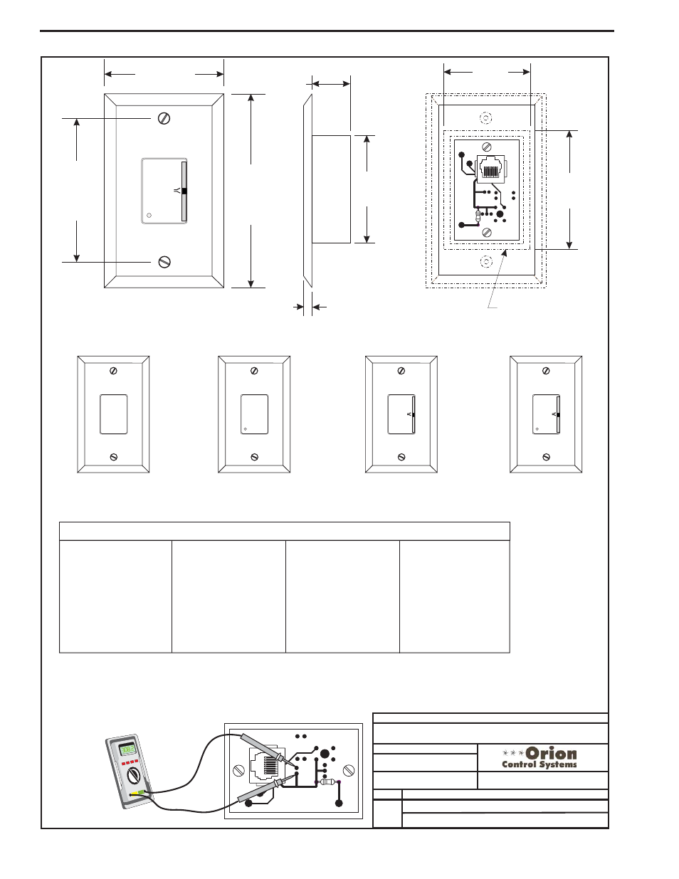
Room Sensor Typical Dimensions
*Chart Notes:
1. Use the resistance column to check the thermistor sensor while disconnected from the controllers (not powered). Connect as shown below.
2. Use the voltage column to check sensors while connected to powered controllers. Read voltage with meter set on DC volts. Place the sensor
leads as shown in the illustration below. If the voltage is above 5.08 VDC, then the sensor or wiring is "open." If the voltage is less than 0.05
VDC, the sensor or wiring is shorted.
O
O
O
A
A
A
O
O
O
R
R
R
L
L
L
M
M
M
E
E
E
E
E
E
C
C
C
W
W
W
R
R
R
R
R
R
OVR
OVR
OVR
0.25“
2.75“
2.00“
Wall Cut-Out Dimensions
When Sensor Is To Be
Mounted Without
Handy Box (By Others)
2.75“
3.25“
OE210-02
OE211-02
OE212-02
OE213-02
Modular Room Sensor -
Plain
Modular Room Sensor
With Override
Modular Room Sensor
With Setpoint Adjust
Modular Room Sensor
With Setpoint Adjust
& Override
R2
PJ1
R1
THERM1
REV 0
YS101858
MODULAR
SENSOR
R2
PJ1
R1
THERM1
REV
0
YS101858
MODULAR
SENSOR
+
-
T
SHLD
+
-
Modular Room Sensor Wiring