Hardware description, Front view (with ac power), Hardware description -2 – Quintum Technologies Tenor Call Relay SP User Manual
Page 20: Front view (with ac power) -2, Power (led)
2-2
P/N 480-0048-00-10
Chapter 2: Hardware Components
Hardware Description
Call Relay SP is a rack mountable device which provides connections to two different sites: Ethernet LAN and
a PC. The unit is available with either AC or DC power.
For the AC unit, the front side of the chassis provides access to the CPU card, the rear side exposes a power
cord connection and an on/off switch.
For the DC unit, the front side of the chassis provides access to the CPU card; the rear side exposes circuit
breakers, power receptacles and power plugs.
See below for a description of each.
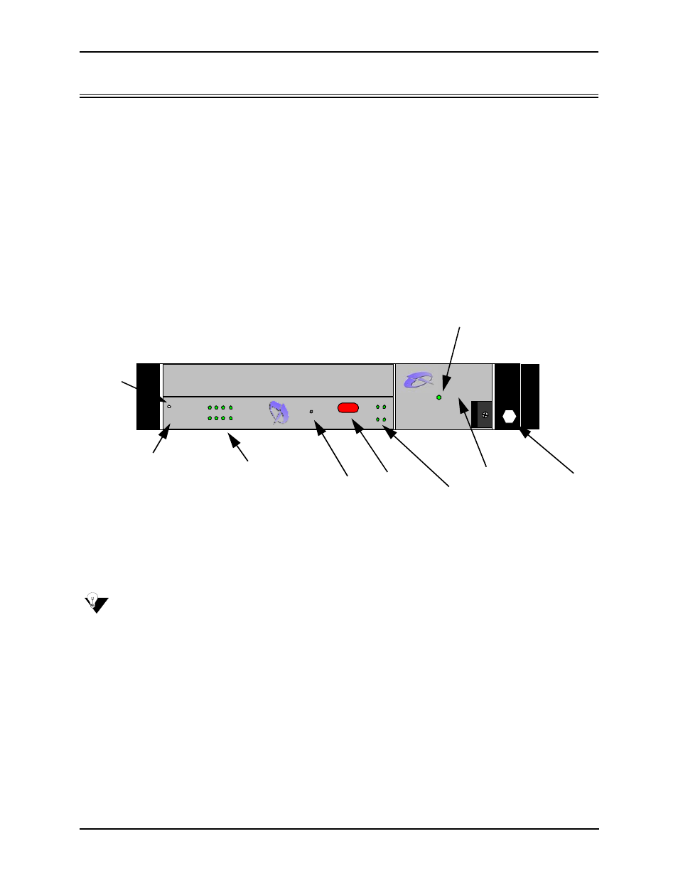
Front View (with AC power)
Figure 2-1 Front (with AC power)
CPU Card. The CPU card is a single slot Compact PCI (Peripheral Component Interconnect) controller card
which provides the central management functionality for the Call Relay SP unit. The controller card is the call
routing engine for the system and coordinates all activity within the chassis, including system resource man-
agement/monitoring.
NOTE:
All Input/Output ports and connections for the CPU card are located on the rear panel of the card.
The CPU provides an interface for transferring VoIP data. As the central point of system resource manage-
ment, the CPU card implements the intelligent call routing and IP call signaling. The card also acts as an inter-
face through which the user is able to perform network and system management functions, such as resetting
the system, connecting to an Ethernet hub/switch, or connecting to a PC. In addition, LEDs provide a high
level indication of system and chassis activity.
Hot Swap LED. For future use.
Ethernet LEDs. The CPU card contains four Link and TX/RX Status LEDs, viewable from the front of the
chassis, to provide a high level indication of the system operational mode and chassis activity, including alarm
activity. Each Link LED relates to one Ethernet line on the rear of the cards.
Reset. Resets the CPU card along with the entire unit.
A.C. Power Supply
Power
QUINTUM
TEC H N OLOGIES, IN C .
TM
TE
CHNO
L
O
G
IE
S
, I
NC.
QU
IN
T
U
M
TM
CP
U
4
8
3
7
26
15
Al
a
rm
CP
U
2
St
a
tu
s
PC
I
R
ese
t
10/
10
0
Et
h
er
n
et
Li
nk
TX
/R
X
Ho
t S
w
a
p
Hot Swap LED
Power Supply
CPU
Card
Ethernet LEDs
Reset
IR Port
Card Activity LEDs
Wrist Strap
Ground
Socket
Power (LED)