Quintum Technologies Tenor Call Relay SP User Manual
Page 37
P/N 480-0048-00-10
3-7
Chapter 3: Installation
1. Check to ensure the source of the DC feeds to the Call Relay SP are turned off and the circuit breakers are
in the off position prior to making any changes to the power wire connections.
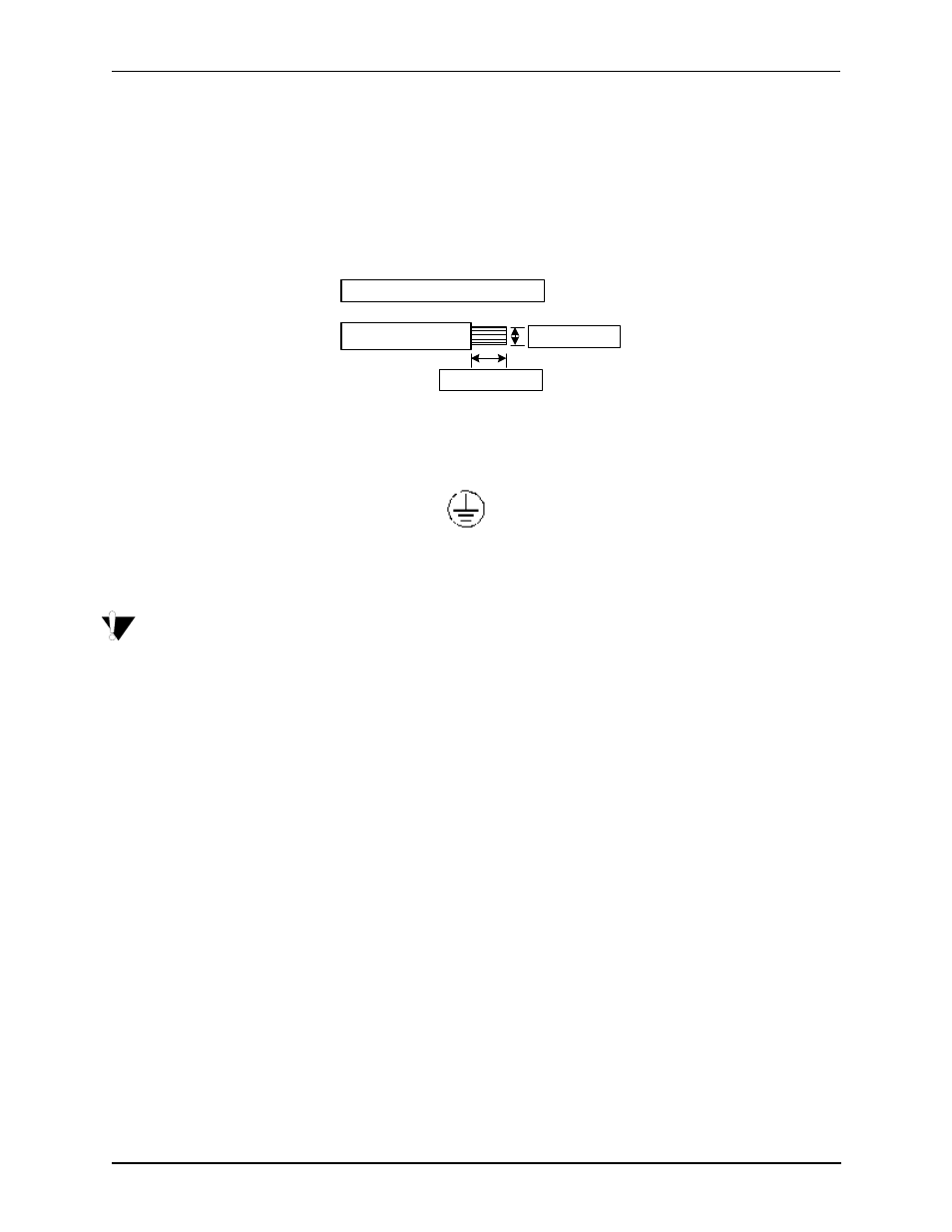
2. Beginning with the wire to be attached to Earth Ground, strip away 0.33 in. (8.5 mm) of insulation. See
Figure 3-5 Strip away wire
3. Insert the wire into the connector in the position labeled as shown in Figure 3-6.
Figure 3-6 Connector position
4. Secure by tightening the clamping screw with a straight blade screwdriver of size 0.023x 0.137 (0.6 x
3.5mm). Screws must be torqued between a minimum of 4.4 lbs in (0.5 Nm) and a maximum of 5.3 lbs in
(0.6 Nm).
WARNING:
Do not over torque the screws.
5. Repeat steps 2-4 for the RTN and -48V source connections, in the following order: Ground, RTN, -48.
6. Close the on-site (over current) protection device to supply power to the inlet (s) of the Call Relay SP.
7. Close the circuit breaker(s) on the Call Relay SP. Verify that the STATUS LEDs on the power supplies are
green a few seconds after turn on.
0.25" (7.0mm)
DC Power Wire Strip Length
10 - 14 AWG
0.33 (8.5 mm)