Cpu replacement, Replace cpu module, Cpu replacement -8 – Quintum Technologies Tenor Call Relay SP User Manual
Page 86: Replace cpu module -8
8-8
P/N 480-0048-00-10
Chapter 8: Diagnostics/Maintenance
CPU Replacement
Replace CPU module
The unit continually monitors the CPU for proper functioning. Any errors are reported through the associated
LEDs or an alarm. The alarm may indicate that the CPU is healthy but one of the lines is not functioning prop-
erly.
If the alarm indicates that the CPU has failed, and needs to be replaced, replace as follows:
1. Turn the system off via power switch or the circuit breaker on the rear of the unit.
2. Install the ESD Ground Strap on your wrist and into the socket. (See Chapter 3: Installation for more
information).
3. Loosen the handle anchoring screws with a #1 Phillips screwdriver (there is one screw in each handle).
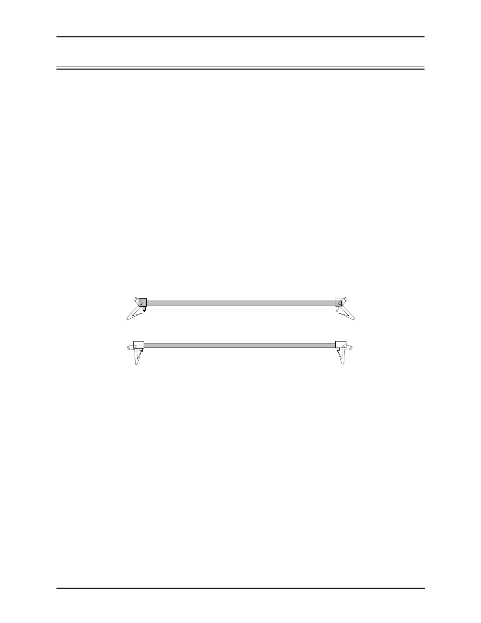
4. With a thumb on top left and right inserter/extractor handles, gently pull the handles away from each other
to the open position until you feel the CPU release (see Figure 8-1).
5. Use both hands to slide the card from the chassis. Place the card in an antistatic bag and seal it.
Figure 8-1 CPU Board Handles
6. With the handles in the open position (see Figure 8-1), slide the new card firmly into the slot until the card
feels engaged.
7. Push the inserter/extractor handles in toward each other to the closed position to lock the card in place.
8. Turn the power switch to on and the blue LED will light momentarily and extinguish.
9. Re-tighten the handle anchoring screws, one in each handle with a #1 Phillips screwdriver.
Side View - Open Position
Side View - Closed Position