Front view (with dc power), Front view (with dc power) -6, Power (led) alarm (led) – Quintum Technologies Tenor Call Relay SP User Manual
Page 24
2-6
P/N 480-0048-00-10
Chapter 2: Hardware Components
Front view (with DC power)
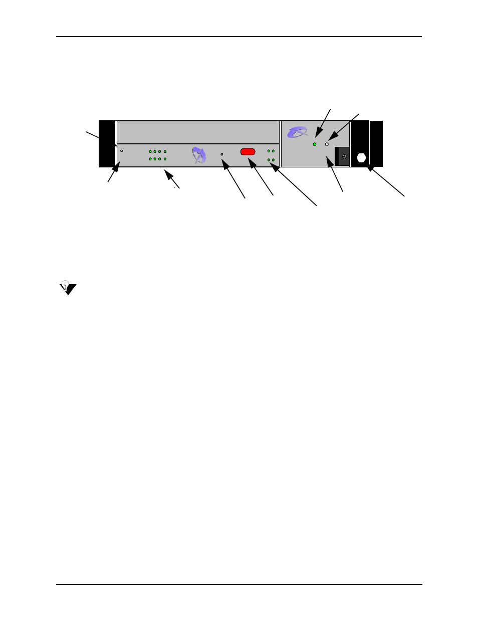
Figure 2-5 Front (with DC power)
CPU Card. The CPU card is a single slot Compact PCI (Peripheral Component Interconnect) controller card
which provides the central management functionality for the Call Relay SP unit. The controller card is the call
routing engine for the system and coordinates all activity within the chassis, including system resource man-
agement/monitoring.
NOTE:
All Input/Output ports and connections for the CPU card are located on the rear panel of the card.
The CPU provides an interface for transferring VoIP data throughout the system and communicating with the
other network cards via PCI bus. As the central point of system resource management, the CPU card imple-
ments the intelligent call routing and IP call signaling. The card also acts as an interface through which the
user is able to perform network and system management functions, such as resetting the system, connecting to
an Ethernet hub/switch, or connecting to a PC. In addition, LEDs provide a high level indication of system and
chassis activity.
Hot Swap LED. For future use.
Ethernet LEDs. The CPU card contains four Link and TX/RX Status LEDs, viewable from the front of the
chassis, to provide a high level indication of the system operational mode and chassis activity, including alarm
activity. Each Link LED relates to one Ethernet line on the rear of the cards.
Reset. Resets the CPU card along with the entire chassis.
Port. For future use.
Card Activity LEDs. LEDs provide a high level indication of the CPU card activity. Basic definitions follow.
See Chapter 8: Diagnostics/Maintenance for a detailed description and troubleshooting purposes.
• Alarm. Indicates an alarm has been generated.
• Status. Green light. When a user logs in through telnet, the LED turns to amber.
• CPU. Green light indicates the CPU bus is active.
• PCI. Green light indicates that the local PCI bus is busy.
Power Supply. DC Power Supply.
D.C. Power Supply
Power Alarm
QUINTUM
TEC H N OLOGIES, IN C .
TM
TE
CHNO
L
O
G
IE
S
, I
NC.
QU
IN
T
U
M
TM
CP
U
4
8
3
7
26
15
Al
a
rm
CP
U
2
St
a
tu
s
PC
I
R
ese
t
10/
10
0
Et
h
er
n
et
Li
nk
TX
/R
X
Ho
t S
w
a
p
Hot Swap LED
Power Supply
CPU
Card
Ethernet LEDs
Reset
Port
Card Activity LEDs
Wrist Strap
Ground
Socket
Power (LED)
Alarm (LED)