M1-3 components, M1-3 components -5 – Verilink M1-3 (880-503136-001) Product Manual User Manual
Page 15
M1-3 Overview
Verilink M1-3 User Manual
1-5
M1-3
Components
and
following components:
M1-3 Application
Module
The front-panel application module contains the multiplexer
microprocessor including flash firmware. The front module
supports the following management ports:
•
Craft (L
OCAL
) port for fault isolation and test.
•
Primary and extension management ports for transferring ACP
messages between shelves or Node Manager.
The front panel also supports three status LEDs labeled SYS, T1,
and T3.
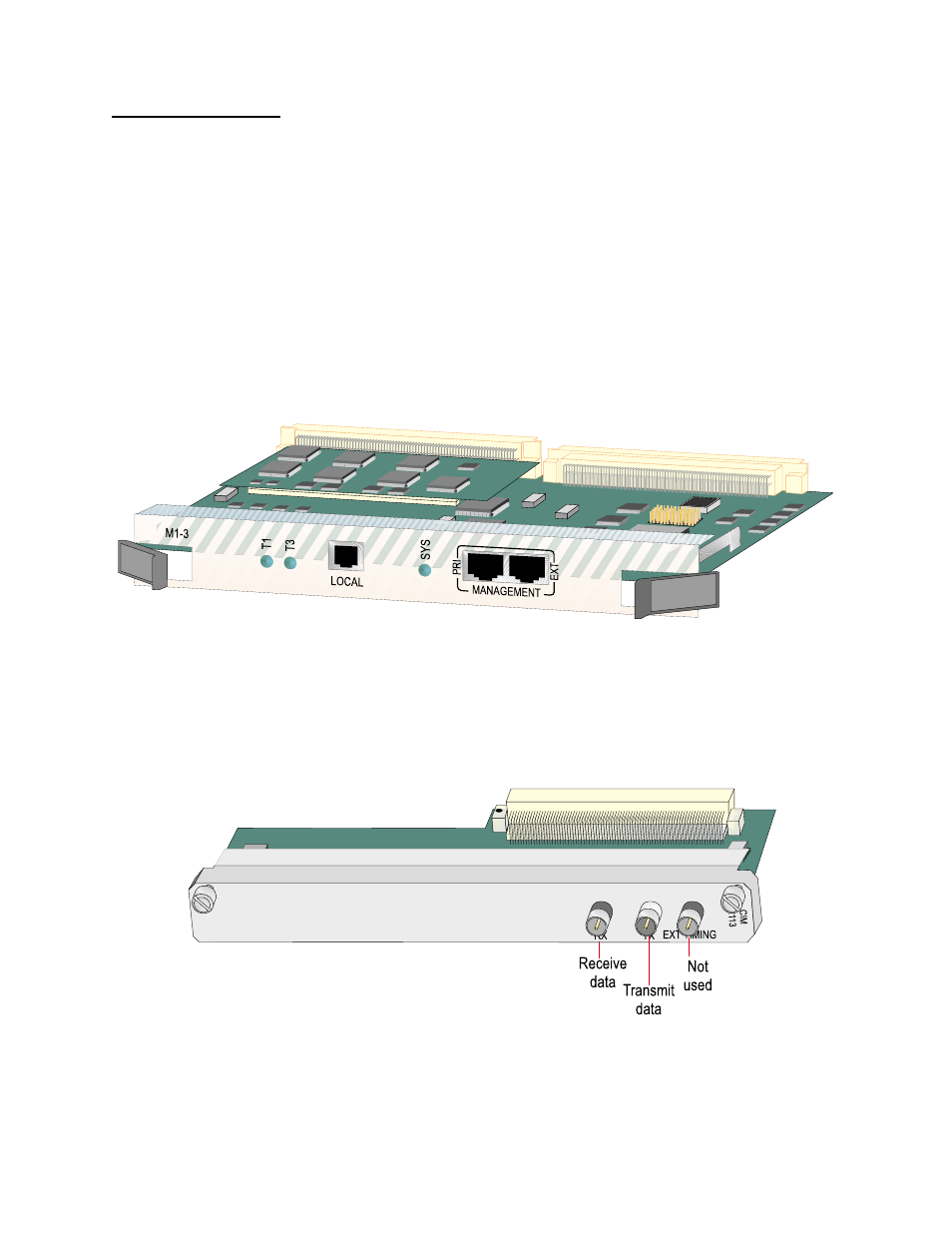
Figure 1-3 M1-3 Front Panel
CIM 3113 Rear
Connector Module
A detachable rear connector interface module (CIM) connects to the
M1-3 module. The CIM provides three interface connectors (
) including two coaxial DS3 ports (TX and RX), and a coaxial
external timing port. The RJ-11 diagnostics port and two mini D-
sub connectors are not used.
Figure 1-4 M1-3 Connector Interface Module