Quick set-up, Chapter – Verilink M1-3 (880-503136-001) Product Manual User Manual
Page 19
Verilink M1-3 User Manual
2-1
Chapter
2
Quick Set-Up
The Quick Set-Up section provides the steps necessary to install
and configure an M1-3 module. Refer to the menu options
described in Chapter 3, “
” when
determining the settings and values for your configuration.
This chapter also provides an example configuration and makes the
following assumptions:
•
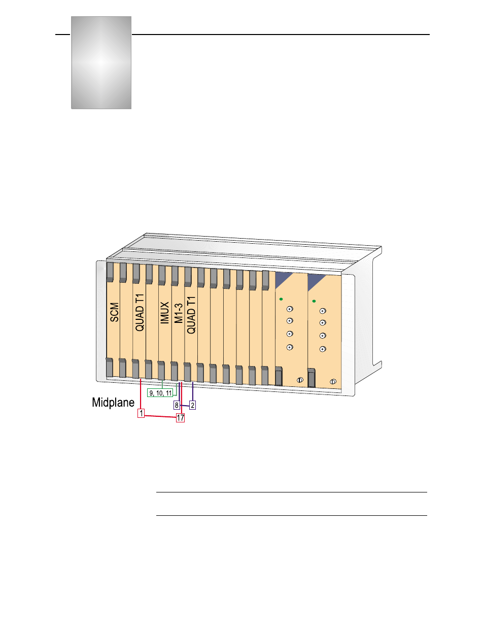
That an SCM is in slot 1 with a shelf address of 1. An M1-3
multiplexer is in slot 6, a QUAD T1 is installed in slot 3, and an
IMUX module is in slot 5 (
).
Figure 2-1 Configuration Example Module Placement
The following circuits are developed in the circuit build example
shown in
•
The M1-3 T1 number 17 to the QUAD T1, net1.
•
The M1-3, T1 number 9, 10, and 11 to the IMUX module.
NOTE: Adjust one or more of these values to adapt the quick set-up
to your configuration.