Circuit manager, Circuit manager -14, Near end far end – Verilink M1-3 (880-503136-001) Product Manual User Manual
Page 44
M1-3 Configuration Options
3-14
Verilink M1-3 User Manual
Circuit Manager
Circuit building is a primary function of the SCM controller
module. For information on circuit building, refer to the
SCM User
Manual
shows an example of an M1-3 circuit. Only 64K
circuits are supported.
shows the T1s used in this T3 port.
Each T1 can have a unique configuration.
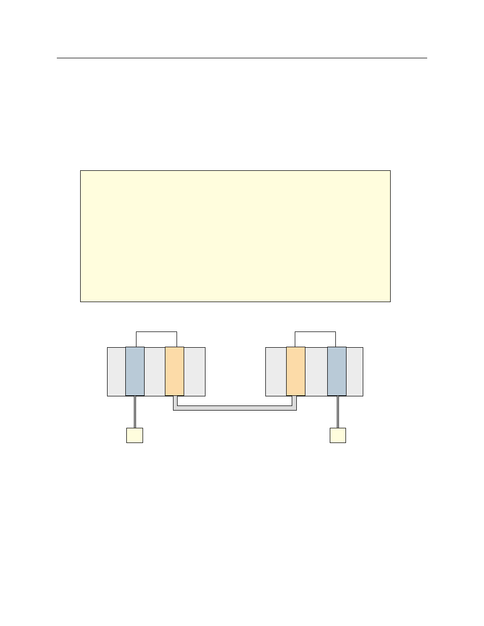
Figure 3-15 M1-3 to IMUX Circuit
M1-3
IMUX
M1-3
IMUX
CPE
CPE
Circuit: im_m13
Near End
Far End
-- ADD CIRCUIT MENU [0,1] SCM Firmware 1.17 --
N) name: im_m13
SP) src port: [0,7] IMUX data
- - port data rate - -
[ 1536 * 8 = 12288 kbps ]
Bus: AUT
S) setup
A [127.127.127.67] [0,1] SCM>
M) mode: 64k
DP) dst port: [0,10] HSM m13
DT) - - T1 map selection - -
01 02 03 04 05 06 07 08
.. .. .. .. .. .. .. ..
.. .. .. .. .. .. .. ..
.. .. ..
T3
T1
T1
Circuit: im_m13
Timeslots 1-8
Timeslots 1-8