Hng-fec – Wavecom W61PC V7.5.0 User Manual
Page 172
162
Transmission Modes
WAVECOM Decoder W61PC/LAN Manual V7.5
Parameter
Value
Remarks
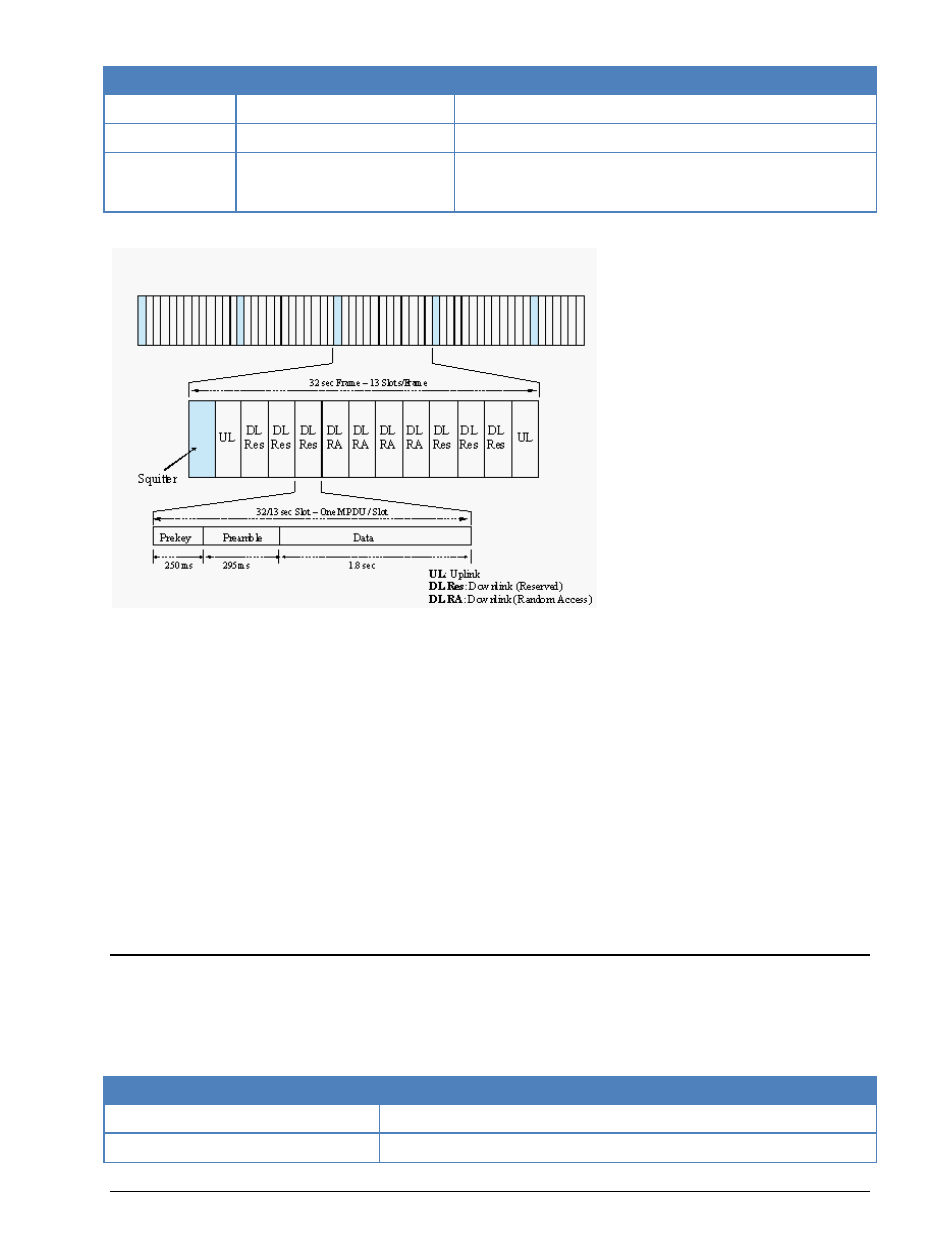
Pre-key
249 ms
1440 Hz single tone
Preamble
295 ms
Known BPSK symbols for synchronization purposes
Data
1.8 sec (single slot) or 4.2 sec
(double slot)
Data section structured in data-probe pairs (45 M-PSK sym-
bols each: 30 user data symbols and 15 known BPSK symbols
for synchronization purpose)
The following diagram shows the TDMA slotted frame structure.
The HF-ACARS decoder detects each slot with the characteristic pre-key (1440 Hz single tone), uses the
preamble to synchronize the slot, eliminates various distortions in the HF communication channel, config-
ures several components of the decoder, demodulates the user data section and decodes it according to
the HFDL protocol interpreter.
Each message is finally output on the screen in Squitter (SPDU) format, Uplink MPDU format (from ground
station to aircraft) or Downlink MPDU format (from aircraft to ground station).
Only when a HFDL slot is successfully detected, the decoder enters the Traffic state, otherwise it remains
in the Sync state.
Usually an HFDL station sends the signal with USB setting. However the decoder has the possibility to pro-
cess signals in both USB and LSB settings. This can be done by setting the polarity in the menu neither to
NOR for USB and INV for LSB signals.
The center frequency of the decoder should be set to 1440 Hz when the receiver is set to the nominal fre-
quency of the ground station. A small frequency difference will be automatically compensated by the de-
coder. However, the center frequency can be tuned by ±400 Hz from its nominal setting.
There are two internal system configuration files for the display of HFDL messages, hfacars.txt and hfa-
cars.dat. These files should not be modified by the user.
HNG-FEC
HNG-FEC uses a 15 bit code, the first 5 bits corresponding to the ITA-2 alphabet. The first and last bits of
this code word are inverted (Inv, Nor, Nor, Nor, Nor, Inv). The remaining 10 bits are used for error detec-
tion and correction. Error correction is done by table look up of the character which closest matches the
one that was received in error.
Parameter
Value
Frequency range
HF
Operation modes
Broadcast /Simplex FEC