Fax and data transmission, Modem functionality – Wavecom W61PC V7.5.0 User Manual
Page 291
WAVECOM Decoder W61PC/LAN Manual V7.5
Modem and FAX modes
281
voice, the North American channel utilizes one bit for signaling (“robbed bit” signaling). Two different algo-
rithms are used for sampling, A law and mu law.
Large organizations use E1 or T1 subscriber loops to connect their PBX (Private Branch Exchanges) to a
PSTN central office.
The line interface is either two coaxial lines or two balanced pairs, one for each direction.
ISDN digital loop
The Integrated Services Digital Network (ISDN) is the oldest attempt of extending the digital infrastruc-
ture to the subscriber. ISDN comes in two flavors, the Basic Rate Interface (BRI) delivering 2 x 64 kbps
channels + 16 kbps channeling totaling 144 kbps and Primary Rate Interface delivering 30 voice channels
+ 2 signaling channels equaling an E1 of 2.048 Mbps.
At the subscriber premises a BRI is terminated in a Network Termination box which converts the line sig-
nal from the line T interface to a local synchronous interface, the S four-wire interface supporting up to
eight devices of which two may be active at the same time. The S bus carries 40 V. Analogue equipment
connects to the S bus via a Terminal Adapter (TA).
The local loop (not the S bus) is a normal balanced two-wire pair carrying the T interface line signals, at a
voltage at between 25 and 96 VDC.
Fax and data transmission
In order to transmit the fax and modem data, the signals must be processed in such a way that they are
adapted and ruggedized for the transmission over noisy and disturbed telephone lines. Transmit and re-
ception processing takes place in devices called modems – a combination of “modulator” and “demodula-
tor”. The properties of various modems are standardized through ITU (International Telecommunications
Union) V-series recommendations. Fax standards are laid down in a number of T-series recommendations.
Modem functionality
The techniques used to make the data more robust include framing, scrambling, error detection and cor-
rection and compression,and line conditioning using probing and training signals, which are used to adjust
equalizers and echo cancellers at the far end to the actual phase, frequency and amplitude characteristics
of the line.
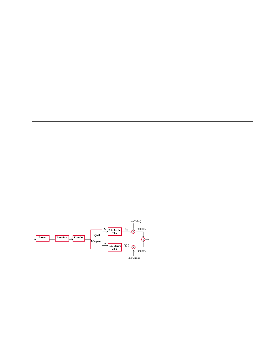
A schematic of the transmission section of a typical modem using phase modulation is shown below. In-
coming data is framed as HDLC frames, scrambled to facilitate bit synchronization, and then encoded. The
encoded signal is then mapped to the phase changes (and for QAM also to amplitude changes) and used
to modulate a quadrature carrier.