Wavecom W61PC V7.5.0 User Manual
Page 233
WAVECOM Decoder W61PC/LAN Manual V7.5
Transmission Modes
223
Baud
Rate
User da-
ta
rate
(bps)
User data
rate (bps)
FEC coding
rate
Interleaver
No. of unknown
8-phase
sym-
bols (User Data)
No. of known 8-
phase symbols
(Channel Probe)
2400
1200
1 (BPSK)
No coding
ZERO
32
16
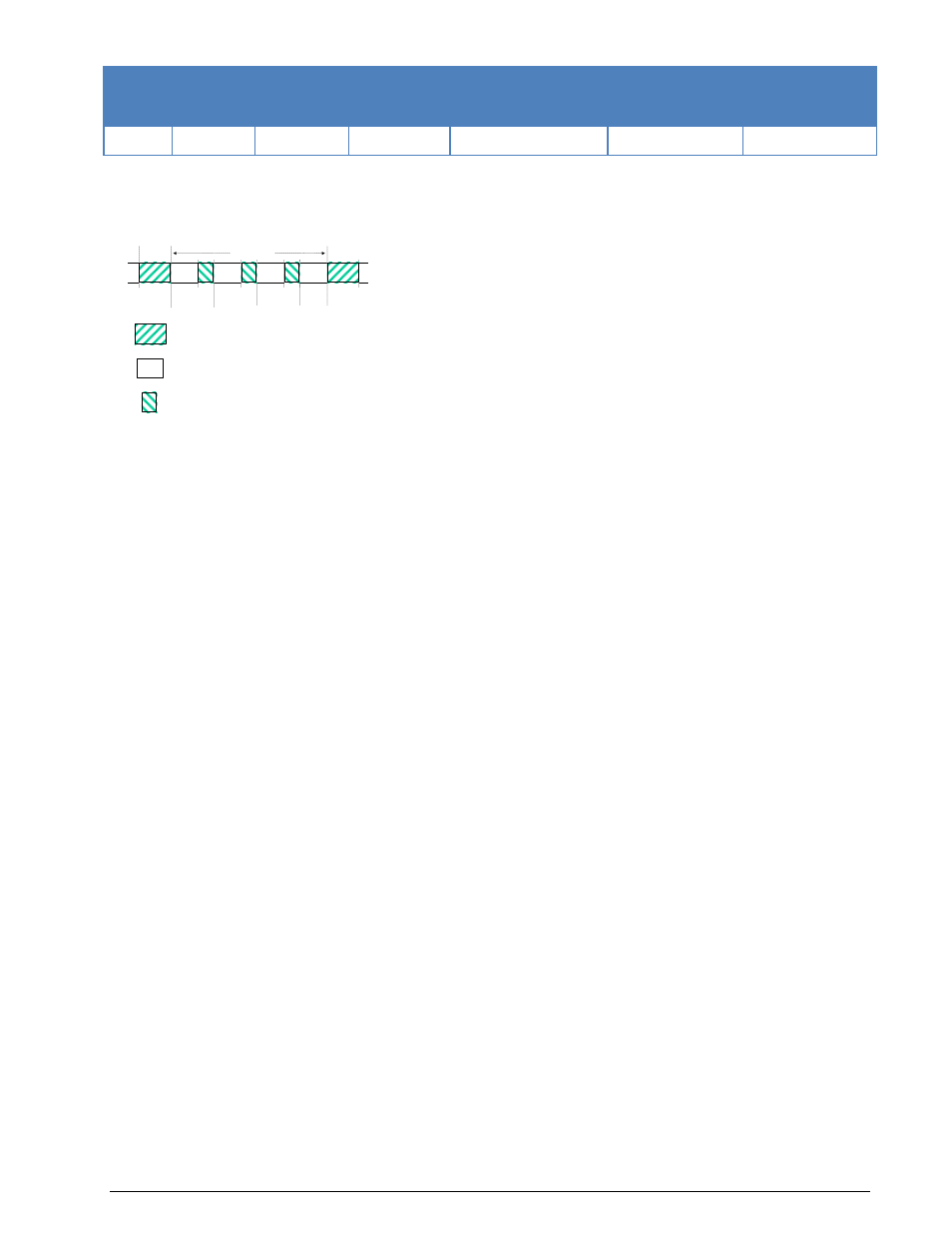
The user data is transmitted using a continuous frame structure. Each frame begins with a 33.33 ms pre-
amble containing 80 symbols, the next 176 symbols are divided into four 32-symbol data segments and
three 16-symbol channel probe segments.
At the end of transmission, a certain bit-pattern (in hexadecimal notation, 4B65A5B2, MSB first) is sent to
mark the end of message (EOM). The EOM sequence is followed by flush bits, which are for FEC coder
flushing and for the complete transmission of the remainder of the interleaver data block.
In most cases FEC and interleaver are used to combat the effects of fading, frequency shift, multipath ef-
fects and burst noise. User data is in this case first FEC encoded, interleaved, then mapped into PSK sym-
bol and transmitted in 32 symbol data segment. The 16 symbol channel segment transmitted between
every data segment has a known PSK pattern. Its purpose is to keep the demodulator, mainly the equaliz-
er, on track in spite of adverse propagation conditions during the HF transmission.
After the 176 symbol data-probe segment another frame beginning with the same 80-symbol preamble
follows immediately. This frame structure makes the synchronization of the demodulator in the mid of the
transmission very easy.
The STANAG-4285 decoder processes all the above configurations. This should be set manually in the
Frame Format menu.
Generally STANAG-4285 transmits the user data in binary mode, i.e. it does not care what type of binary
data is transmitted. This should be defined by the higher layer using the STANAG 4285 mode. For this
reason the decoder displays the user data in BINARY, HEX, ASCII ASYNC, ASCII ASYNC (7 Data bits
and No Stop bit) or ASCII SYNC format selected from Options | Message Type.... The decoder stops
displaying data after the EOM bit pattern is received.
In the HEX display mode, the decoded binary data is just display as it is, MSB first.
In ASCII ASYNC mode, the bit stream is searched with ASCII ASYNC structure, i.e. one start-bit (0), 8 da-
ta-bits and at least one stop-bit (1). The 8 data-bits are LSB first. In addition to the EOM pattern, the dis-
play will stop if more than 300 NULL characters are received or if the asynchronous data structure is vio-
lated more than 80 times.
In ASCII ASYNC (7 Data bits and No Stop bit) mode, the bit stream is searched with another ASYNC struc-
ture, i.e. one start-bit (0), 7 data-bits. The 7 data-bits are LSB first. In addition to the EOM pattern, the
display will stop if more than 300 NULL characters are received.
In ASCII SYNC mode, each 8 bits (LSB first) represent one ASCII character. The display will stop if the
EOM pattern is received or if more than 20 NULL characters are received.
Tuning the decoder
The mode decoder can process signal in both SSB settings: USB and LSB. This can be set by toggling the
Polarity field: NOR means USB and INV means LSB signal.
The center frequency of the decoder should be set to 1800 Hz when the receiver is correctly tuned to the
sending station. Small frequency deviations are automatically tracked and compensated during the decod-
ing. The center frequency of the decoder can be adjusted to ± 400 Hz from its normal setting. By using
the bar-graph, any remaining frequency difference can be compensated for by fine-tuning of the receiver
frequency or by adjusting the center frequency of the decoder.
16
16
16
32
32
32
32
80
symbols
80
symbols
Block 1
Block 2
Block 3
Block 4
T = 106.66 ms
33.33 ms
80
symbols
16
32
Preamble
Data symbols
Channel probe symbols