Wavecom W61PC V7.5.0 User Manual
Page 236
226
Transmission Modes
WAVECOM Decoder W61PC/LAN Manual V7.5
Symbol rate
2400 Bd
Receiver settings
Data, CW, USB, LSB
Signal source(s)
AF, IF
The modulation technique used in this mode is based on the operating conditions encountered by naval
broadcasts.
The technology utilizes binary phase shift keying (BPSK) of a single tone 1800 Hz sub-carrier with a con-
stant modulation speed of 2400 Bd. Through the use of BPSK modulation and a FEC coding rate of 1/4,
the effective user data rate is 300 bps.
Baud Rate
User data rate (bps)
Bits per symbol (M-PSK)
FEC coding rate
Interleaver
2400
300
1 (BPSK)
1 / 4
long
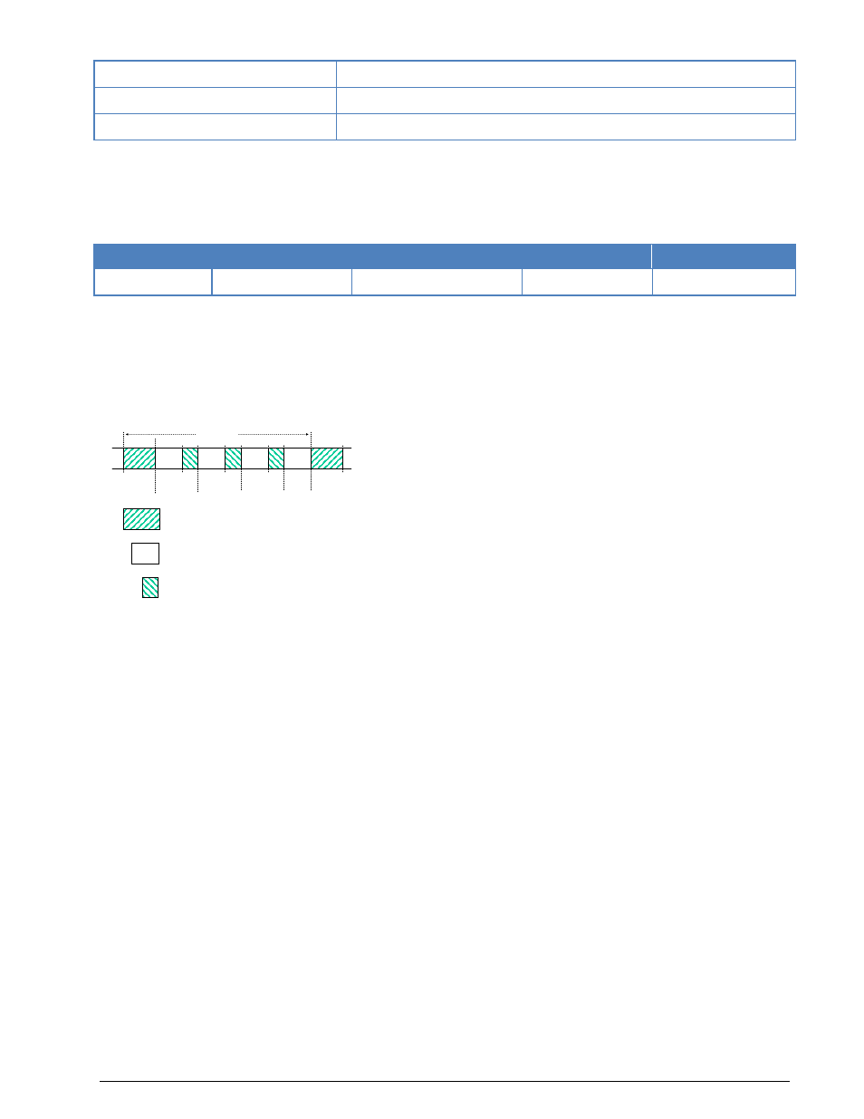
The user data is transmitted using a continuous frame structure with 213.33 ms per frame. Each frame
starts with a preamble containing 80 symbols. The following 176 symbols are divided into four 32-symbol
data segments and three 16-symbol channel probe segments.
The 176-symbol data-probe segment immediately follows the next frame, beginning with the same 80-
symbol preamble. This repeated frame structure enables synchronization of the demodulator at any time
of transmission.
At the end of transmission, an EOM bit pattern (0x4B65A5B2, MSB first) is sent to mark the end of mes-
sage. The EOM sequence is followed by flush bits, to flush the FEC coder and to complete the transmission
of the remainder of the interleaver data block.
FEC and interleaving is used to combat the effects of fading, Doppler spread, multipath and burst noise.
User data is first FEC encoded, interleaved, then mapped into BPSK symbols and transmitted in 32 symbol
data segments. The 16 symbol channel probe segment transmitted between each succeeding data seg-
ment has a known PSK pattern. Its purpose is to keep the demodulator, mainly the equalizer, on track in
spite of adverse propagation conditions during the HF transmission.
This STANAG mode is either used to transmit data in transparent binary mode or as ASCII text. For this
reason the decoder displays the user data in HEX, ASCII ASYNC, ASCII ASYNC (7 Data bits and No
Stop bit) or ASCII SYNC format selected from Options | Message Type.... The decoder stops display-
ing traffic after the EOM bit pattern is received.
In the HEX display mode, the decoded binary data is displayed as hex values, MSB first.
In ASCII ASYNC mode, the bit stream is correlated with an ASCII ASYNC structure, i.e. one start-bit (0), 8
data bits and at least one stop bit (1). The 8 data bits are displayed LSB first. In addition to the EOM pat-
tern, the display will stop if more than 300 NULL characters are received or if the asynchronous data
structure is violated more than 80 times.
In ASCII ASYNC (7 data bits and no stop bit) mode, the bit stream is correlated with another ASYNC struc-
ture, i.e. one start bit (0) and 7 data bits. The 7 data bits are displayed LSB first. In addition to the EOM
pattern, the display will stop if more than 300 NULL characters are received.
In ASCII SYNC mode, each 8 bits (LSB first) represent one ASCII character. The display will stop when ei-
ther the EOM pattern was recognized or more than 20 NULL characters have been received.
16
16
16
32
32
32
32
80
80
Block 1
Block 2
Block 3
Block 4
T = 213.33 ms
80
16
32
Preamble symbols
Data symbols
Channel probe symbols
Preamble