Mpls te tunnel using rsvp-te configuration example, Network requirements – H3C Technologies H3C SR8800 User Manual
Page 102
91
------------------------------------------------------------------
FEC In/Out Label In/Out IF Vrf Name
-/- 30/NULL GE3/1/1/-
[RouterA] display mpls static-cr-lsp
total static-cr-lsp : 1
Name FEC I/O Label I/O If State
Tunnel3 3.3.3.3/32 NULL/20 -/GE3/1/1 Up
[RouterB] display mpls static-cr-lsp
total static-cr-lsp : 1
Name FEC I/O Label I/O If State
Tunnel3 -/- 20/30 GE3/1/1/GE3/1/2 Up
[RouterC] display mpls static-cr-lsp
total static-cr-lsp : 1
Name FEC I/O Label I/O If State
Tunnel3 -/- 30/NULL GE3/1/1/- Up
NOTE:
On an MPLS TE tunnel configured using a static CR-LSP, traffic is forwarded directly based on label at the
transit nodes and egress node. Therefore, it is normal that the FEC field in the sample output is empty on
Router B and Router C.
7.
Create a static route for routing MPLS TE tunnel traffic.
[RouterA] ip route-static 3.2.1.2 24 tunnel 3 preference 1
Perform the display ip routing-table command on Router A. You can find a static route entry with
interface Tunnel3 as the outgoing interface.
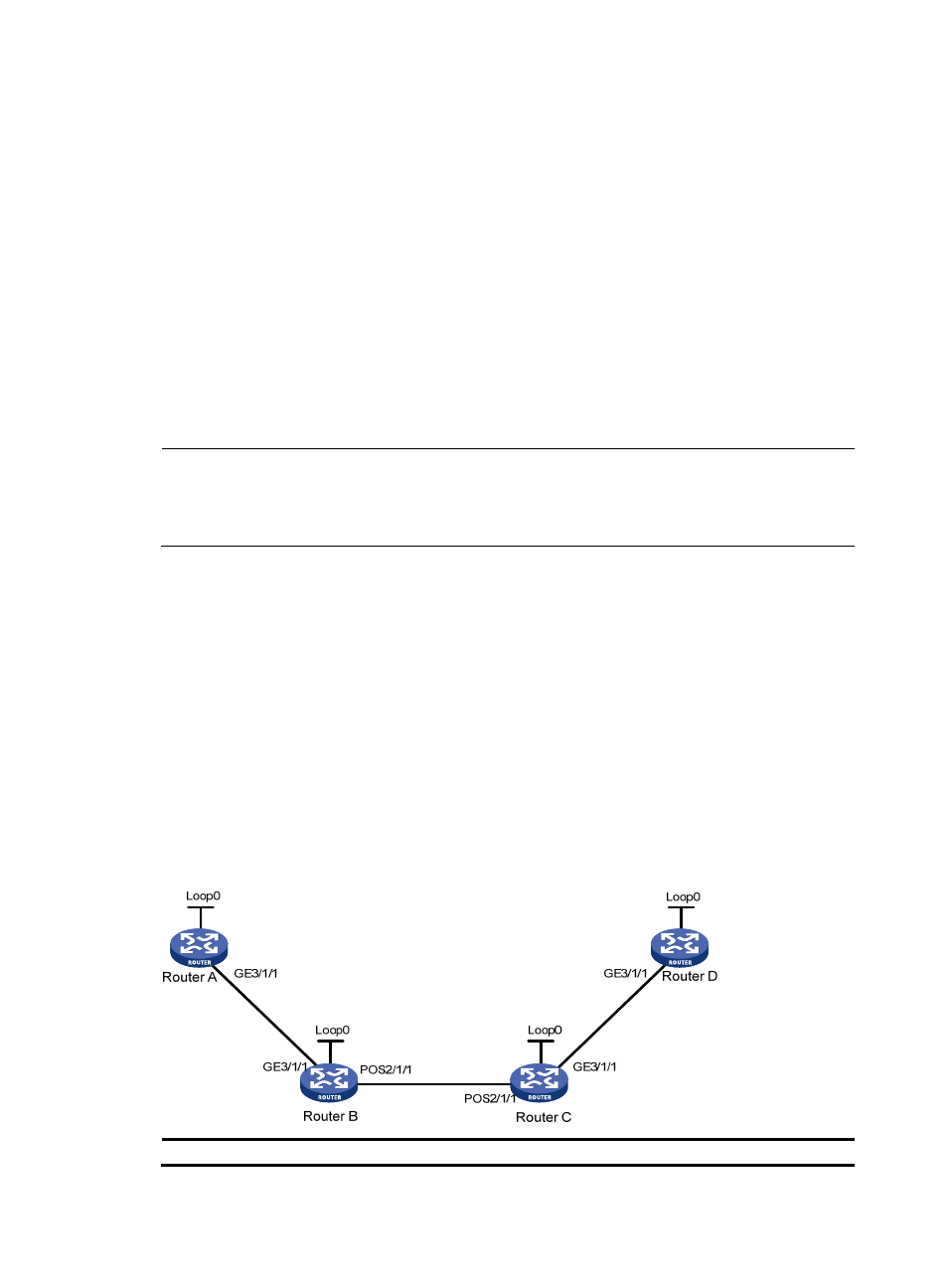
MPLS TE tunnel using RSVP-TE configuration example
Network requirements
Router A, Router B, Router C, and Router D are running IS-IS and all of them are Level-2 routers.
Use RSVP-TE to create a TE tunnel with 2000 kbps of bandwidth from Router A to Router D, ensuring that
the maximum bandwidth of each link that the tunnel traverses is 10000 kbps and the maximum
reservable bandwidth is 5000 kbps.
Figure 25 Network diagram
Device Interface IP
address
Device
Interface
IP address