Mpls l3vpn configuration task list, Figure 73 – H3C Technologies H3C SR8800 User Manual
Page 255
244
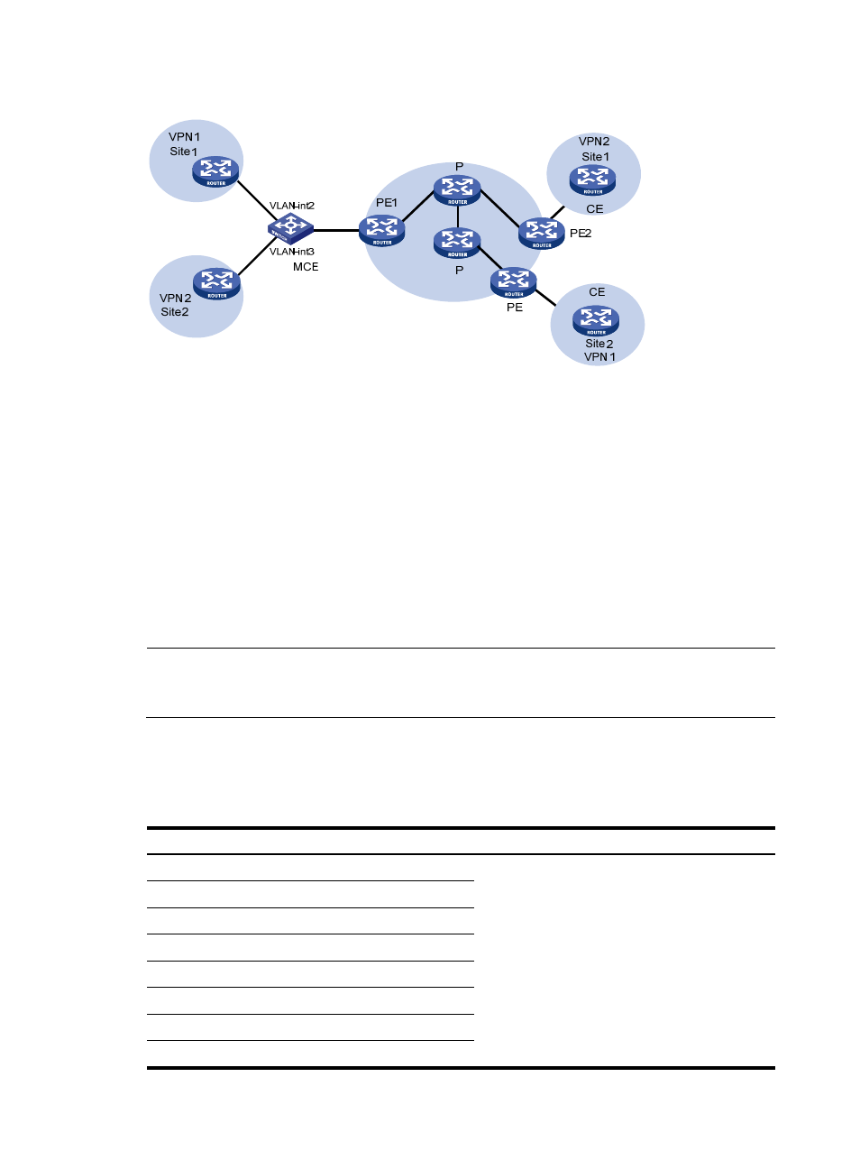
Figure 73 Network diagram for the MCE function
Establish a tunnel between the two sites of each VPN.
Create a routing table for VPN 1 and VPN 2 respectively on the MCE device, and bind VLAN-interface
2 to VPN 1 and VLAN-interface 3 to VPN 2. When receiving a route, the MCE device can determine the
source of the routing information according to the number of the receiving interface, and adds it to the
corresponding routing table.
You must also bind PE 1’s interfaces/subinterfaces connected to the MCE to the VPNs in the same way.
The MCE connects to PE 1 through a trunk link, which permits packets of VLAN 2 and VLAN 3 with VLAN
tags carried. In this way, PE 1 can determine the VPN a received packet belongs to according to the
VLAN tag of the packet and sends the packet through the corresponding tunnel.
You can configure static routes, RIP, OSPF, IS-IS, EBGP, or IBGP between MCE and VPN site and between
MCE and PE.
NOTE:
To implement dynamic IP assignment for DHCP clients in private networks, you can configure DHCP server
or DHCP relay agent on the MCE. The IP address spaces for different private networks cannot overlap.
MPLS L3VPN configuration task list
Complete the following tasks to configure MPLS L3VPN:
Task Remarks
By configuring basic MPLS L3VPN, you can
construct simple VPN networks over an MPLS
backbone.
To deploy special MPLS L3VPN networks, such as
inter-AS VPN, nested VPN, and multi-role host, you
also need to perform some specific configurations in
addition to the basic MPLS L3VPN configuration.