Configuring h-vpls with lsp access, Network requirements – H3C Technologies H3C SR8800 User Manual
Page 183
172
[PE2] l2vpn
[PE2-l2vpn] mpls l2vpn
[PE2-l2vpn] quit
# Configure the VPLS instance aaa that uses LDP signaling.
[PE2] vsi aaa static
[PE2-vsi-aaa] pwsignal ldp
[PE2-vsi-aaa-ldp] vsi-id 500
[PE2-vsi-aaa-ldp] peer 1.1.1.9
[PE2-vsi-aaa-ldp] quit
[PE2-vsi-aaa] quit
# Configure the VPLS instance bbb that uses BGP signaling.
[PE2] vsi bbb auto
[PE2-vsi-bbb] pwsignal bgp
[PE2-vsi-bbb-bgp] route-distinguisher 100:1
[PE2-vsi-bbb-bgp] vpn-target 111:1
[PE2-vsi-bbb-bgp] site 2 range 10
[PE2-vsi-bbb-bgp] quit
[PE2-vsi-bbb] quit
# Configure interface GigabitEthernet 3/1/2 and bind VPLS instance aaa or bbb to the interface.
[PE2] interface GigabitEthernet 3/1/2
// To bind VPLS instance aaa to interface GigabitEthernet 3/1/2:
[PE2-GigabitEthernet3/1/2] l2 binding vsi aaa
// To bind VPLS instance bbb to interface GigabitEthernet 3/1/2:
[PE2-GigabitEthernet3/1/2] l2 binding vsi bbb
[PE2-GigabitEthernet3/1/2] quit
After completing previous configurations, issue the display vpls connection command on the PEs. You will
see that a PW connection in up state has been established.
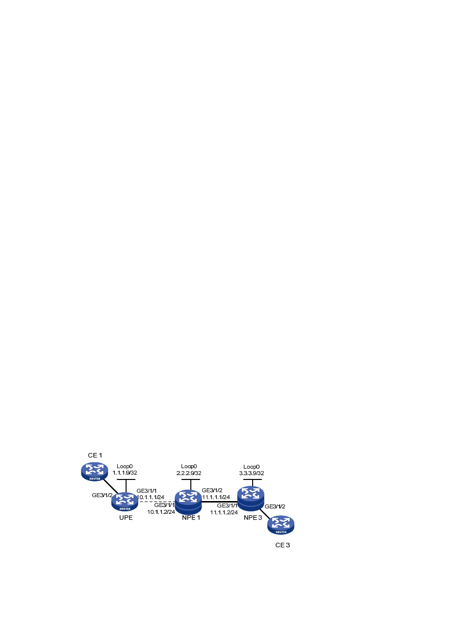
Configuring H-VPLS with LSP access
Network requirements
Create a U-PW between UPE and NPE 1 and an N-PW between NPE 1 and NPE 3. Create an LDP VPLS
instance aaa.
Figure 43 Network diagram