Ipv6 mpls l3vpn configuration examples, Configuring ipv6 mpls l3vpns, Network requirements – H3C Technologies H3C SR8800 User Manual
Page 382: Configuration procedure
371
IPv6 MPLS L3VPN configuration examples
Configuring IPv6 MPLS L3VPNs
Network requirements
•
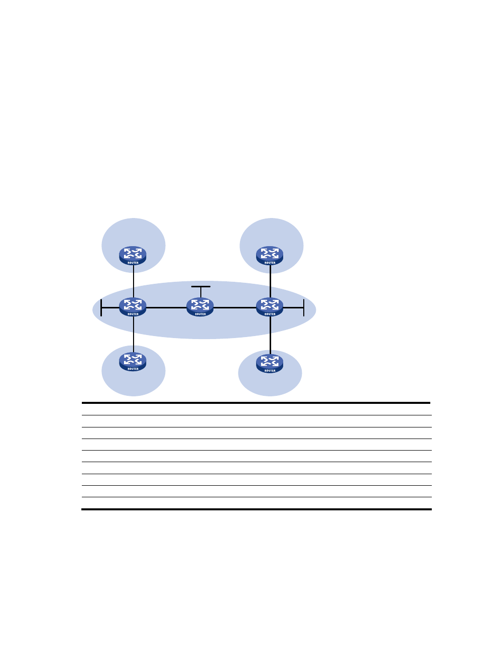
CE 1 and CE 3 belong to VPN 1. CE 2 and CE 4 belong to VPN 2.
•
VPN 1 uses VPN target attributes 111:1. VPN 2 uses VPN target attributes 222:2. Users of different
VPNs cannot access each other.
•
EBGP is used to exchange VPN routing information between CEs and PEs.
•
PEs use OSPF to communicate with each other and use MP-IBGP to exchange VPN routing
information.
Figure 87 Network diagram
Device
Interface
IP address
Device
Interface
IP address
CE 1
GE4/1/1
2001:1::1/96
P
Loop0
2.2.2.9/32
PE 1
Loop0
1.1.1.9/32
POS2/1/1 172.1.1.2/24
GE4/1/1
2001:1::2/96
POS2/1/2
172.2.1.1/24
GE4/1/2
2001:2::2/96
PE 2
Loop0
3.3.3.9/32
POS2/1/1
172.1.1.1/24
GE4/1/1 2001:3::2/96
CE 2
GE4/1/1
2001:2::1/96
GE4/1/2
2001:4::2/24
CE 3
GE4/1/1
2001:3::1/96
POS2/1/1 172.2.1.2/24
CE 4
GE4/1/1
2001:4::1/96
Configuration procedure
1.
Configure OSPF on the MPLS backbone to achieve IP connectivity among the PEs and the P router.
# Configure PE 1.
<PE1> system-view
[PE1] interface loopback 0
[PE1-LoopBack0] ip address 1.1.1.9 32
CE 1
Loop0
Loop0
Loop0
PE 1
PE 2
GE4/1/1
GE4/1/1
GE4/1/2
GE4/1/1
POS2/1/1
GE4/1/1
GE4/1/2
GE4/1/1
GE4/1/1
CE 3
CE 2
CE 4
POS2/1/1
POS2/1/2
POS2/1/1
VPN 1
VPN 1
VPN 2
VPN 2
MPLS backbone
AS 65410
AS 65430
AS 65420
AS 65440
P