2 design, 3 ventilation, Design – SMA SC 200 Installation User Manual
Page 19: Ventilation
SMA Solar Technology AG
Installation
Installation Guide
SC20_25_35-IEN094521
19
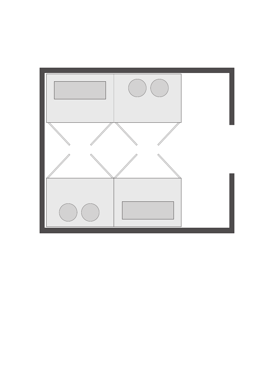
4.2.2 Design
The following illustration is a schematic of the layout of an electrical service room with a
Sunny Central 250HE.
4.3 Ventilation
An incoming air supply is required to cool the Sunny Central. In order to guarantee safe operation
and the maximum of feed-in power, the permitted ambient temperature must be observed.
The required air is drawn through the switch cabinet doors and is blown out via the top or the rear
wall of the cabinet unit depending on the Sunny Central model. This means that the devices can be
installed right next to one another. See the "Sunny Central Installation Requirements" (separate
document) for the air requirements as well as appropriate wall clearances. Filters are installed at the
air inlet openings. They clean the inlet air.
If the volume of air at the installation site of the Sunny Central is insufficient, then on-site measures must
be taken to provide greater quantities of air (ventilation grilles, blowers, fans, etc.).
The inlet air must satisfy the requirements of classification 3S2. If a Sunny Central is used in a
chemically-active environment, the inlet air must satisfy the requirements of classification 3C1.
The central inverter can be operated in relative humidity from 15 ... 95 %.