10 connecting the evr resistor (optional), Connecting the evr resistor (optional) – SMA SC 200 Installation User Manual
Page 50
Internal Electrical Connections
SMA Solar Technology AG
50
SC20_25_35-IEN094521
Installation Guide
5.10 Connecting the EVR Resistor (optional)
The EVR resistor increases the maximum permissible DC voltage which may be present at the device's
connection when idle to 1000 V DC. The EVR resistor is mounted on the top of the Sunny Central If
the EVR resistor is used, the exhaust air cannot be routed through the top of the Sunny Central. The
exhaust air is routed through the rear wall.
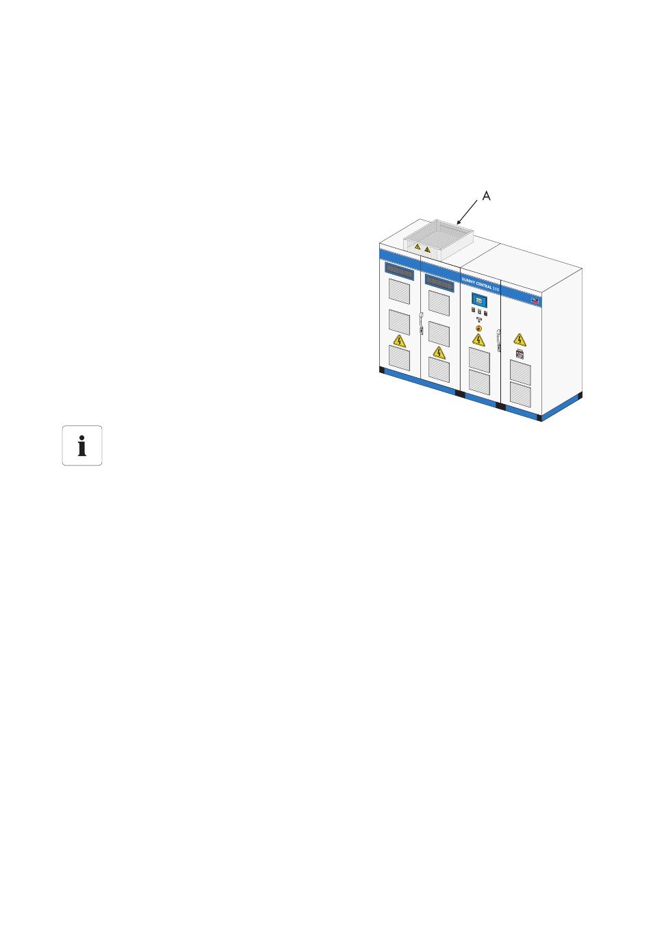
The following diagram shows the position of the EVR
resistor (A) using the Sunny Central 250 as an example.
1. Slide the EVR resistor between the rails onto the top of the Sunny Central.
2. Remove the 9 bolts on the protective grille of the EVR resistor.
3. Remove the protective grille forwards.
4. Connect the PE cable in the EVR resistor to the bolt on the left side.
5. Secure the EVR resistor to the rails using the two bolts on the left and right in the EVR resistor.
6. Connect the power cables (included) as shown in the circuit diagram provided.
7. Secure the protective grille to the EVR resistor using the 9 bolts.
☑ The EVR resistor is connected.
Position of the connection terminals of the EVR resistor.
The exact position of the EVR resistor be determined with the help of the equipment
identifier and the circuit diagram enclosed.