2 sunny central 350, Sunny central 350 – SMA SC 200 Installation User Manual
Page 62
Advertising
External Connections
SMA Solar Technology AG
62
SC20_25_35-IEN094521
Installation Guide
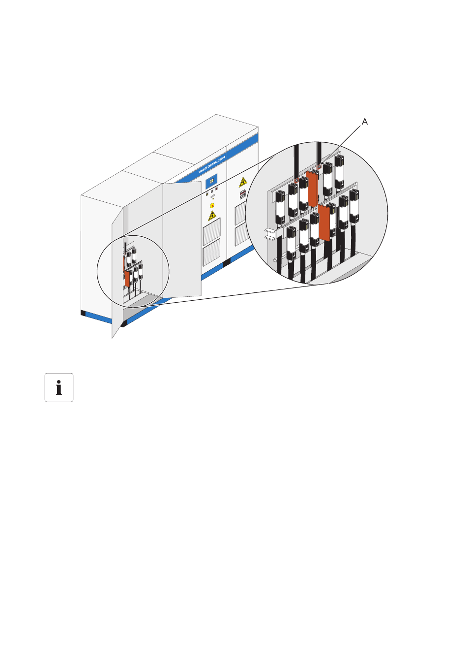
6.5.2 Sunny Central 350
The following diagram shows the connections of the DC inputs in the Sunny Central 350 as an
example.
The DC fuses are arranged in 2 rows. The cables are initially connected to the DC fuses of the rear
mounting plate. The front DC cables cannot be connected to the fuses until the rear DC cables have
been connected.
A
DC cable connection point
Position of the DC inputs
The exact position of the PE rail differs depending on the model. The exact position of the
DC inputs can be determined with the help of the equipment identifier and the circuit
diagram enclosed.
Advertising
This manual is related to the following products: