6 connecting the team cable (optional), Connecting the team cable (optional) – SMA SC 200 Installation User Manual
Page 64
External Connections
SMA Solar Technology AG
64
SC20_25_35-IEN094521
Installation Guide
6.6 Connecting the Team Cable (optional)
The power cables in team connection connect the team leader to the team device. The cables required
(standard length 5 m) are included. If the cable length is insufficient, another cable can be used. This
cable must have a DC voltage resistance of 1000 V and be designed for the expected DC team
current at a nominal output of 100 %. See the following table for the required information on DC team
current.
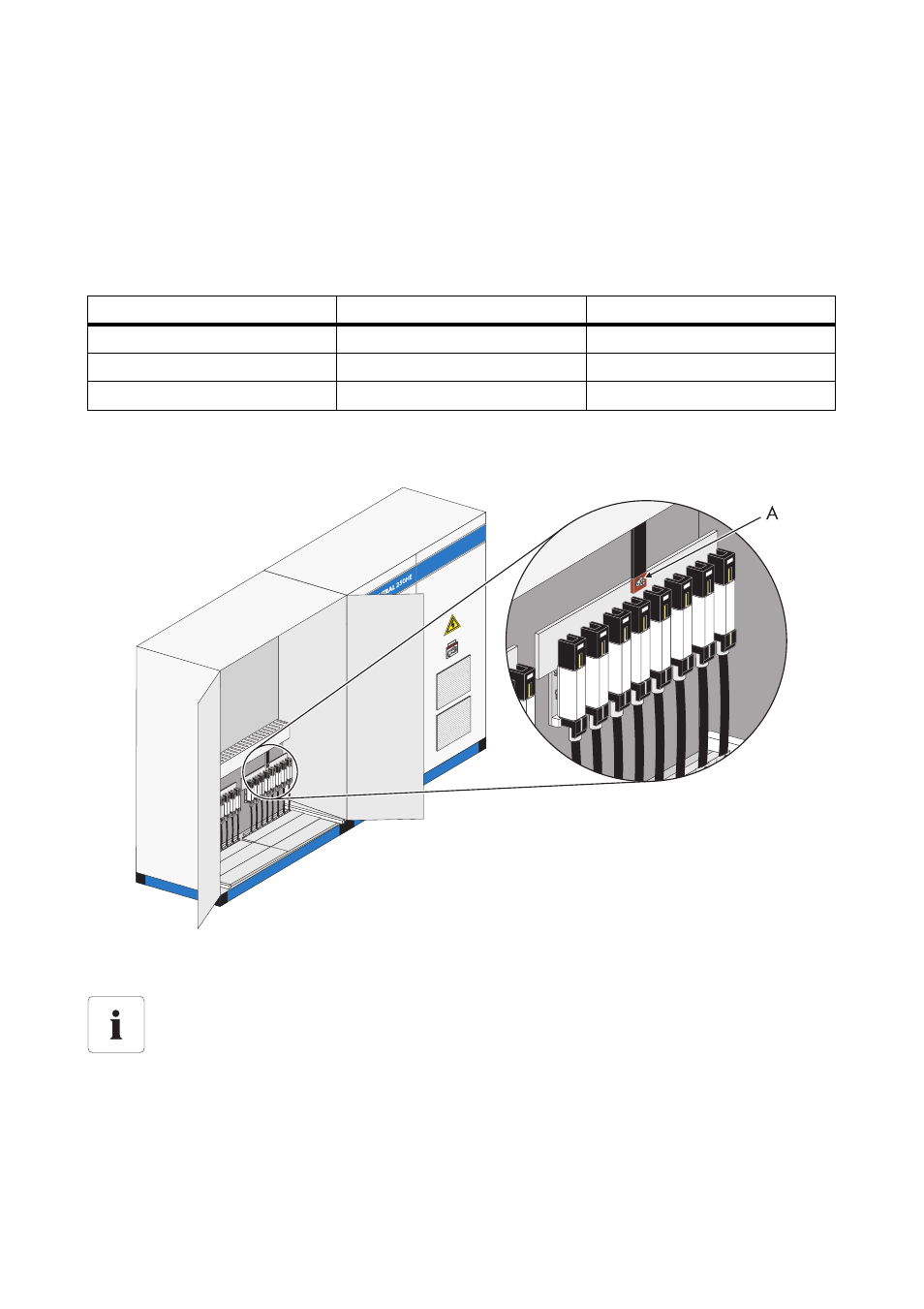
The connection terminals for team connection are located in the cabinet. The following diagram shows
the position of the connection terminals in the Sunny Central 250.
1. Route the cable through the base opening into the DC cabinet.
2. Fit cable lugs to the cable.
3. Connect the cable.
Sunny Central
Maximum DC current input Maximum DC team current
Sunny Central 200
472 A
236 A
Sunny Central 250
591 A
296 A
Sunny Central 350
800 A
400 A
A
Team cable connection point
Position of the connection terminals for the team connection.
The precise position of the connection terminals for the team connection differs depending
on the model. The exact position of the connection terminals can be determined with the
help of the equipment identifier and the circuit diagram enclosed.