SMA SC 200 Installation User Manual
Page 42
Internal Electrical Connections
SMA Solar Technology AG
42
SC20_25_35-IEN094521
Installation Guide
2. Connect the PE cable to the marked grounding bar.
3. Tighten the cable gland (A).
4. Ensure that the PE connection is correct and secure.
☑ The PE cable is connected.
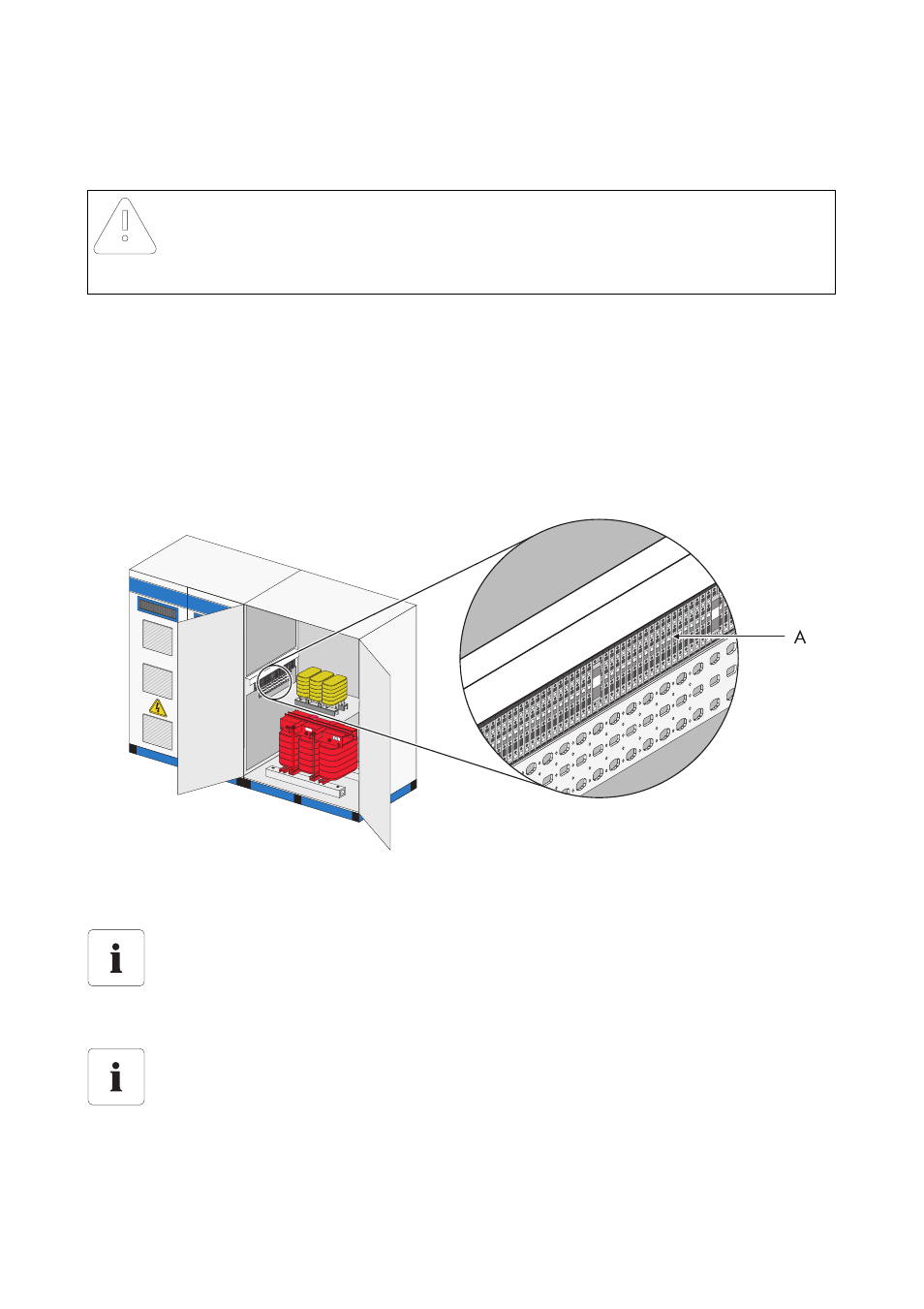
5.4 Connecting the Control Lines on the Transfer Terminal Strip
The control lines are located in the transfer cable duct of the inverter cabinet The control lines are
marked with target designations. The following diagram shows the exact position of the transfer
terminal strip of the Sunny Central 250.
1. Connect the control lines on the transfer terminal strip.
☑ The control lines are connected.
Notice!
Air permeable cable glands cause corrosion in the Sunny Central.
• Tighten the cable gland sufficiently.
A
Transfer terminal strip
Position of the transfer terminal strip
The exact position of the transfer terminal strip differs depending on the model. The exact
position of the individual terminals can be determined with the help of the equipment
identifier and the circuit diagram enclosed.
Allocation of the control lines
The terminal designation is used for unique allocation of the control lines