3 serial interfaces for team connection, Serial interfaces for team connection – SMA SC 200 Installation User Manual
Page 70
External Connections
SMA Solar Technology AG
70
SC20_25_35-IEN094521
Installation Guide
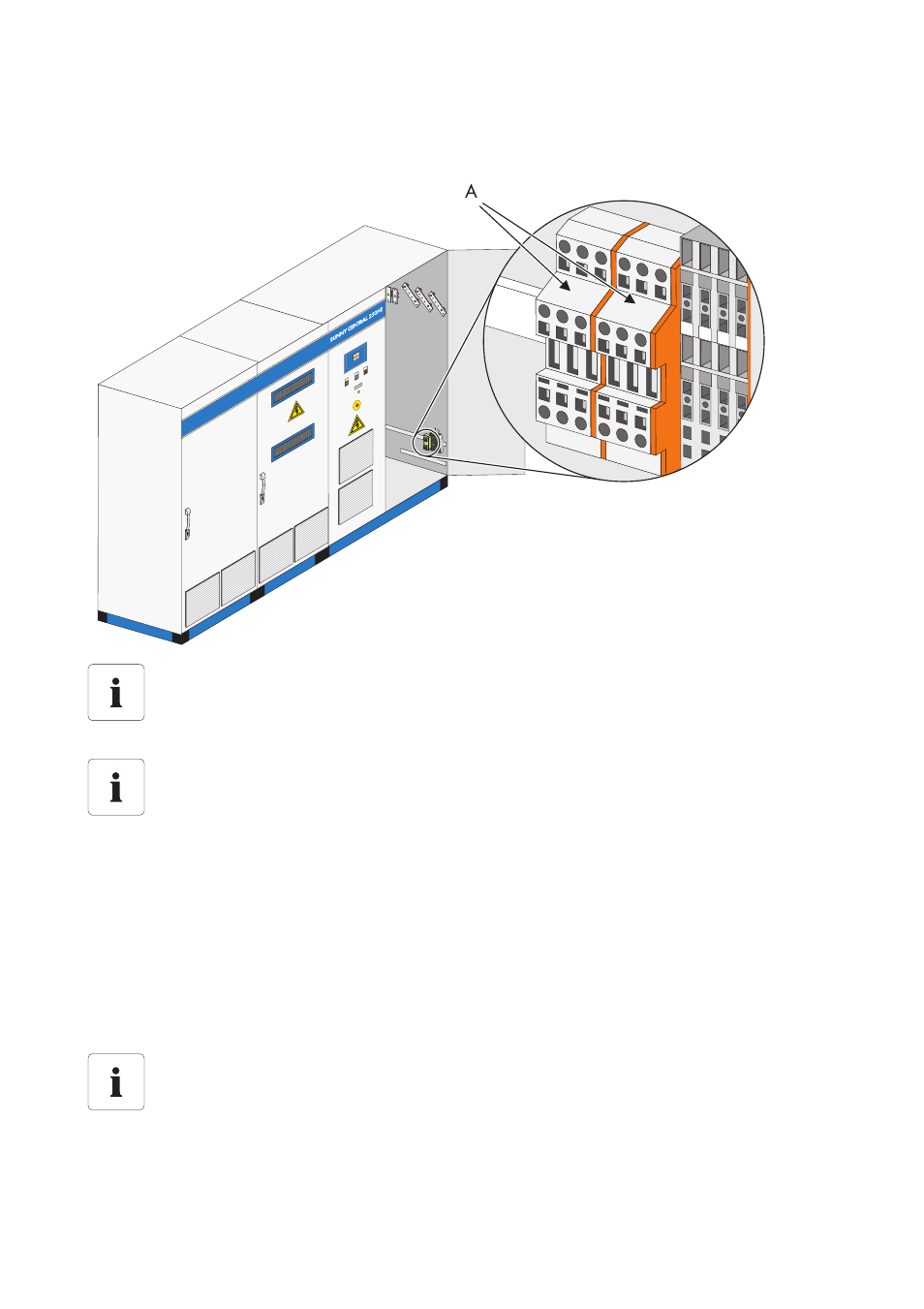
In the Sunny Central 350, the HUBs are guided on terminals (A). The following diagram shows the
position of the connection terminals in the Sunny Central 350.
6.9.3 Serial Interfaces for Team Connection
If team connection is used, communication connection is implemented via the COM1 port on both
Sunny Central Controls. Termination then takes place in the Sunny Central Control. The Sunny Central
Controls are preterminated at the factory.
1. Remove the jumper on the HUB (RS485 OUT).
2. Insert the CAT5 cable (CAT5 cable included).
Position of the HUB
The exact position of the HUB can be determined with the help of the equipment identifier
and the circuit diagram enclosed.
Sunny String-Monitor Technical Description
For further information on the connection of the RS485 cabling, see the Sunny String-
Monitor technical description.
Sunny String-Monitor Technical Description
The documentation provided with the Sunny Central String monitors contains a detailed
description of the installation of the integrated string current monitoring.