3 overview of the analog inputs, 4 handling notes for shielded contacts, Overview of the analog inputs – SMA SC 200 Installation User Manual
Page 66: Handling notes for shielded contacts
External Connections
SMA Solar Technology AG
66
SC20_25_35-IEN094521
Installation Guide
6.7.3 Overview of the Analog Inputs
6.7.4 Handling Notes for Shielded Contacts
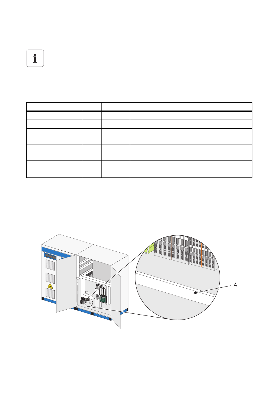
Always use a shielded product for external signal and bus lines. Contact the shield on the shield rail
with the shield clamps over a large area. Use the shield clamps provided for the connection.
The connection terminals of the signal and bus lines are in the AC cabinet. The following diagram
shows the position of the connection terminals in the Sunny Central 250.
Assignment of the analog inputs on the Sunny Central Control
When connecting the analog inputs and for the digital signals, it is obligatory to follow the
included circuit diagram.
The connection is made at the connection terminals. Here, the connections for four-
conductor and two-conductor sensors should be noted and any required measuring
converters should be made available.
Analog Inputs
Ain
Name
Meaning
Customer
Ain 1 ExtSolP
External default nominal value for active power
Customer
Ain 3 ExtSollrr
External radiation sensor
Customer
Ain 4 ExtGlolrr
Pyranometer (measurement of global solar
irradiation)
Customer
Ain 5 ExtAlarm
External alarm input, e.g. for monitoring the
functioning of the medium-voltage transformer
Customer
Ain 6 ExtSolQ
External default nominal value for reactive power
Customer
Ain 8 TmpExt C External temperature sensor / PT 100
A
Connection point for shielded contact rail