2 sunny central 350, Sunny central 350 – SMA SC 200 Installation User Manual
Page 34
Internal Electrical Connections
SMA Solar Technology AG
34
SC20_25_35-IEN094521
Installation Guide
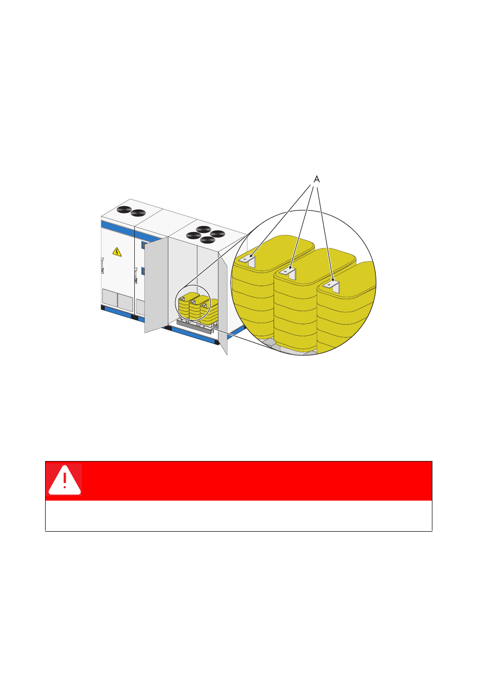
5.2.2 Sunny Central 350
The power cables connect the sine wave filter in the DC- / inverter cabinet with the transformer in the
AC cabinet.
The power cables (U1, V1, W1) are already connected to the sine wave filter and cut to length, so
that the allocations on the transformer are clear.
The following diagram shows the connection points of the power cables on the transformer of the
Sunny Central 350.
Procedure for power cabling:
1. Route the cables through the open side wall above the cabinet base plates into the DC- cabinet.
2. Use cable ties to bind the cables in the base of the switch cabinet.
3. Connect the power cables. Hold the bolts when tightening the nuts.
A
Sine wave filter connection lugs
DANGER!
Danger of fire.
Incorrect connection of the power units can cause fires.
• Observe the sequence when connecting the power units.