SMA SC 200 Installation User Manual
Page 36
Internal Electrical Connections
SMA Solar Technology AG
36
SC20_25_35-IEN094521
Installation Guide
5.2.3 Sunny Central 200 / 250 with the "Protection against
chemically active substances" option
The power cables connect the power units in the DC / inverter cabinet with the sine wave filters in the
AC cabinet. For the Sunny Central 200, 3 power cables must be connected and 6 are required for
the Sunny Central 250.
The power cables (U1, V1, W1) are already connected to the sine wave filter and cut to length, so
that the allocations on the power units are clear.
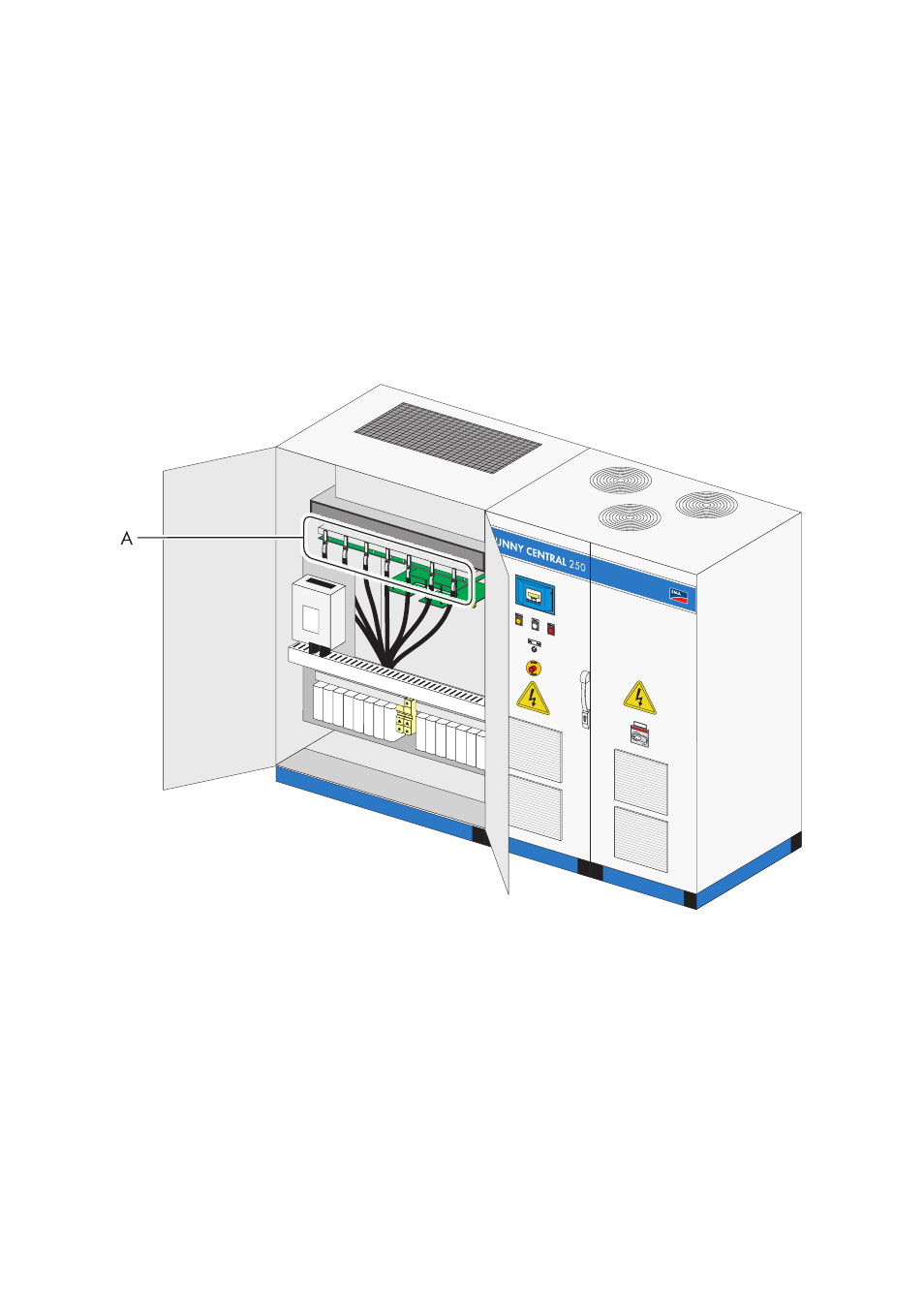
The following diagram shows the connection points of the power cables on the power unit of the
Sunny Central 250.
Procedure for power cabling:
1. Unscrew the protective cover of the power unit.
☑ The protective cover has been removed. The connections on the power unit are now
accessible.
A
Power unit connection lugs