9 sunny central in team connection (optional), Sunny central in team connection (optional) – SMA SC 200 Installation User Manual
Page 47
SMA Solar Technology AG
Internal Electrical Connections
Installation Guide
SC20_25_35-IEN094521
47
5.9 Sunny Central in Team Connection (optional)
2 Sunny Centrals can also be connected to one another as an option. If team connection is used, the
internal team cabling of both switch cabinet units must be connected.
5.9.1 Connecting the Team Cable to
Sunny Central 200 / 250 / 250HE
Team cabling must be implemented for the team leader and the team device.
Team cabling is pre-installed in the AC cabinet. The team cables are in the AC cabinet. The connection
terminals for team cabling are in the DC cabinet.
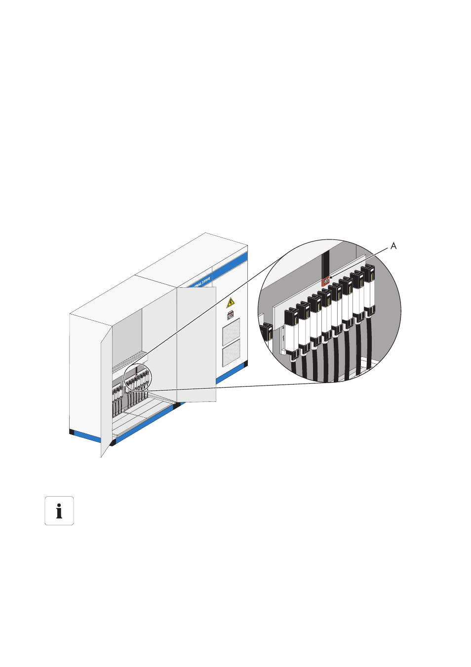
The following diagram shows the position of the connection terminals for team cabling in the
Sunny Central 250.
1. Connect the team cable (L+) to L+ on the busbar.
2. Connect the team cable (L-) to L- on the busbar.
☑ The team cables are connected.
A
Team cable connection point
Position of the connection terminals for team cabling
The exact position of the connection terminals for team cabling can be determined with the
help of the equipment identifier and the circuit diagram enclosed.