Control circuit connections – Yaskawa CIMR-PU User Manual
Page 35
n
Ground Wiring
Follow the precautions below when wiring the ground for one drive or a series of drives.
WARNING!
Electrical Shock Hazard. Make sure the protective earthing conductor complies with technical standards and local safety
regulations. Because the leakage current exceeds 3.5 mA in models 4A0414 and larger, IEC/EN 61800-5-1 states that either the power
supply must be automatically disconnected in case of discontinuity of the protective earthing conductor or a protective earthing conductor
with a cross-section of at least 10 mm
2
(Cu) or 16 mm
2
(Al) must be used. Failure to comply may result in death or serious injury.
WARNING!
Electrical Shock Hazard. Always use a ground wire that complies with technical standards on electrical equipment and minimize
the length of the ground wire. Improper equipment grounding may cause dangerous electrical potentials on equipment chassis, which could
result in death or serious injury.
WARNING!
Electrical Shock Hazard. Be sure to ground the drive ground terminal (200 V class: ground to 100 Ω or less; 400 V class: ground
to 10 Ω or less; 600 V class: ground to 10 Ω or less). Improper equipment grounding could result in death or serious injury by contacting
ungrounded electrical equipment.
NOTICE:
Do not share the ground wire with other devices such as welding machines or large-current electrical equipment. Improper
equipment grounding could result in drive or equipment malfunction due to electrical interference.
NOTICE:
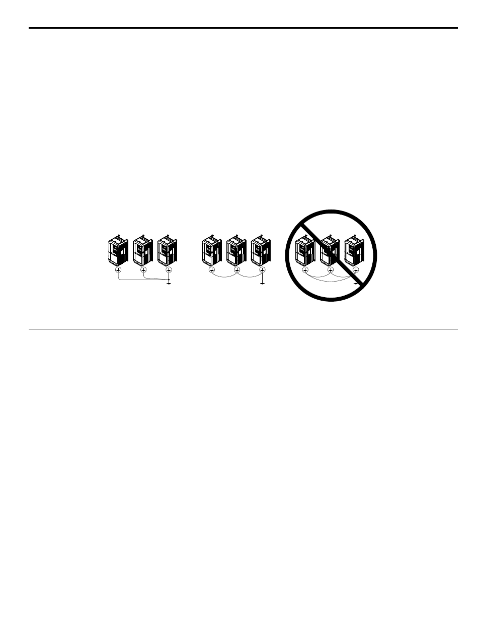
When using more than one drive, ground multiple drives according to instructions. Improper equipment grounding could result in
abnormal operation of drive or equipment.
when using multiple drives. Do not loop the ground wire.
Figure i.11 Multiple Drive Wiring
u
Control Circuit Connections
Drive parameters determine which functions apply to the multi-function digital inputs (S1 to S8), multi-function digital outputs
(M1 to M4), multi-function analog inputs (A1 to A3), and multi-function analog monitor output (FM, AM). The default setting
is listed next to each terminal in
on page
WARNING!
Sudden Movement Hazard. Always check the operation and wiring of control circuits after being wired. Operating a drive with
untested control circuits could result in death or serious injury.
WARNING!
Sudden Movement Hazard. Confirm the drive I/O signals and external sequence before starting test run. Setting parameter
A1-06 may change the I/O terminal function automatically from the factory setting. Failure to comply may result in death or serious injury.
i.3 Electrical Installation Safety
YASKAWA ELECTRIC TOEP YAIP1U 03B YASKAWA AC Drive – P1000 Safety Precautions
35