Sinking/sourcing mode for digital inputs, Terminals a1, a2, and a3 input signal selection, Using external power supply (sink mode) – Yaskawa CIMR-PU User Manual
Page 41: I.3 electrical installation safety
u
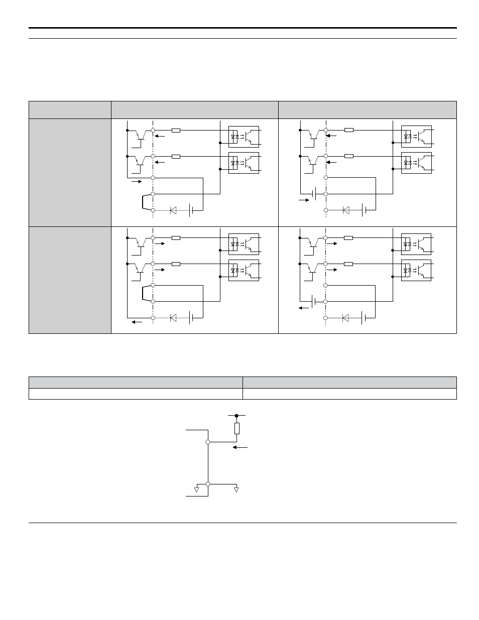
Sinking/Sourcing Mode for Digital Inputs
Use the wire jumper between terminals SC and SP or SC and SN to select between Sink mode, Source mode or external power
supply for the digital inputs S1 to S8 as shown in
(Default: Sink mode, internal power supply).
NOTICE:
Do not short terminals SP and SN. Failure to comply will damage the drive.
Table i.13 Digital Input Sink/Source/External Power Supply Selection
Mode
Drive Internal Power Supply
(Terminals SN and SP)
External 24 Vdc Power Supply
Sinking Mode (NPN)
SC
S8
S7
24 Vdc
SP
SN
SC
S8
S7
24 Vdc
SP
SN
External
24 Vdc
Sourcing Mode (PNP)
SC
S8
S7
24 Vdc
SP
SN
SC
S8
S7
24 Vdc
SP
SN
External
24 Vdc
n
Using External Power Supply (Sink Mode)
The high voltage level of the pulse output signal depends on the external voltage applied. The voltage must be between 12
and 15 Vdc. The load resistance must be adjusted so that the current is lower than 16 mA.
External Power Supply (V)
Load Impedance (kΩ)
12 to 15 Vdc ±10%
1.0 kΩ or higher
MP
AC
Load Impedance
Sink Current
External Power Supply
Figure i.18 Pulse Output Connection Using External Voltage Supply
u
Terminals A1, A2, and A3 Input Signal Selection
Terminals A1, A2, and A3 can be used to input either a voltage or a current signal. Select the signal type using jumper S1 as
. Set parameters H3-01, H3-05, and H3-09 accordingly as shown in
Note:
If terminals A1 and A2 are both set for frequency bias (H3-02 = 0 and H3-10 = 0), both input values will be combined to create the frequency
reference.
i.3 Electrical Installation Safety
YASKAWA ELECTRIC TOEP YAIP1U 03B YASKAWA AC Drive – P1000 Safety Precautions
41