Auto-tuning – Yaskawa CIMR-PU User Manual
Page 48
u
Auto-Tuning
Auto-Tuning automatically sets up the motor data relevant drive parameters. Two different modes are supported.
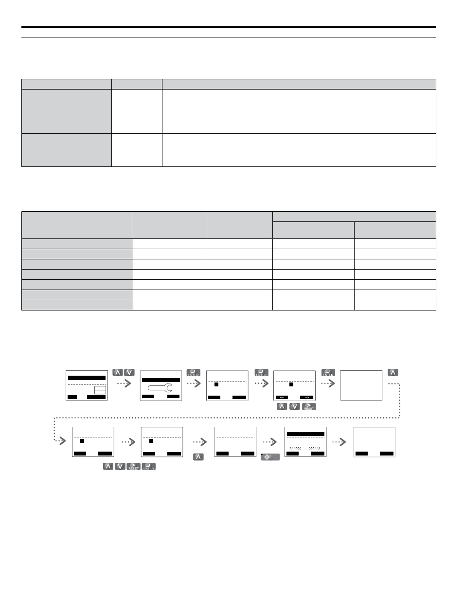
Table i.19 Types of Auto-Tuning for Induction Motors
Type
Setting
Application Conditions and Benefits
Stationary Auto-Tuning for
Line-to-Line Resistance
T1-01 = 2
• The drive is used in V/f Control and other Auto-Tuning selections are not possible.
• Perform when entering motor data manually while using motor cables longer than 50 m.
• Drive and motor capacities differ.
• Tunes the drive after the cable between the drive and motor has been replaced with a cable over
50 m long. Assumes Auto-Tuning has already been performed.
Rotational Auto-Tuning for
V/f Control
T1-01 = 3
• Recommended for applications using Speed Estimation Speed Search or using the Energy Saving
function in V/f Control.
• Assumes motor can rotate while Auto-Tuning is executed. Increases accuracy for certain functions
like torque compensation, slip compensation, Energy Saving, and Speed Search.
The necessary information is usually listed on the motor nameplate or in the motor test report provided by the motor
manufacturer.
Table i.20 Auto-Tuning Input Data
Input Value
Input Parameter
Unit
Tuning Type (T1-01)
2
Line-to-Line Resistance
3
Rotational for V/f Control
Motor rated power
T1-02
kW
YES
YES
Motor rated voltage
T1-03
Vac
–
YES
Motor rated current
T1-04
A
YES
YES
Motor rated frequency
T1-05
Hz
–
YES
Number of motor poles
T1-06
-
–
YES
Motor rated Speed
T1-07
r/min
–
YES
Motor iron loss
T1-11
W
–
YES
WARNING!
Electrical Shock Hazard. High voltage will be supplied to the motor when Stationary Auto-Tuning is performed even with the
motor stopped, which could result in death or serious injury. Do not touch the motor until Auto-Tuning has been completed.
For Auto-Tuning enter the Auto-Tuning menu and perform the steps shown in the figure below. The number of name plate
data to be entered depends on the selected type of Auto-Tuning. This example shows Rotational Auto-Tuning.
- MODE -
End
Tune Successful
DRV
FWD
RESET
Enter the Auto-
Tuning Mode
Select the tuning
method
Set up all
nameplate data
The tuning start
display appear s
During the tuning the
display flashes
After successful tuning
“End” is displayed
Drive mode
display
- A.TUNE -
T1-01=
2
2
Term Resistance
PRG
Entry Accepted
Tuning Mode Sel
FWD
- A.TUNE -
T1-
01
= 2
2
Term Resistance
PRG
Tuning Mode Sel
ESC
FWD
DATA
- MODE -
U1-01= 0.00Hz
U1-02= 0.00Hz
U1-03= 0.00A
DRV
FREF (OPR)
Rdy
JOG
FWD
FWD/REV
LSEQ
LREF
HELP
- MODE -
PRG
Auto-Tuning
DATA
AUTO
FWD
“2”
- A.TUNE -
T1-
07
= 1450RPM
(0 ~ 24000)
PRG
Rated Speed
ESC
FWD
DATA
“1750RPM”
- A.TUNE -
T1-
02
= X.XXkW
(0.00 ~ 650.00)
PRG
Mtr Rated Power
ESC
FWD
DATA
“X.XXkW”
- A.TUNE -
0.00 Hz/ 0.00A
Tuning Ready ?
DRV
Auto-Tuning
ESC
FWD
Press RUN key
- A.TUNE -
X.XX Hz/ X.XXA
DRV
Tune Proceeding
FWD
RUN
When Auto-Tuning cannot be performed, set up the maximum frequency and voltage in the E1-oo parameters and enter the
motor data manually into the E2-oo parameters.
i.5 Start Up
48
YASKAWA ELECTRIC TOEP YAIP1U 03B YASKAWA AC Drive – P1000 Safety Precautions