Fast i/o input data, Parameter access area, Network communications 3-5 – Yaskawa V7 PROFIBUS-DP User Manual
Page 33
Network Communications 3-5
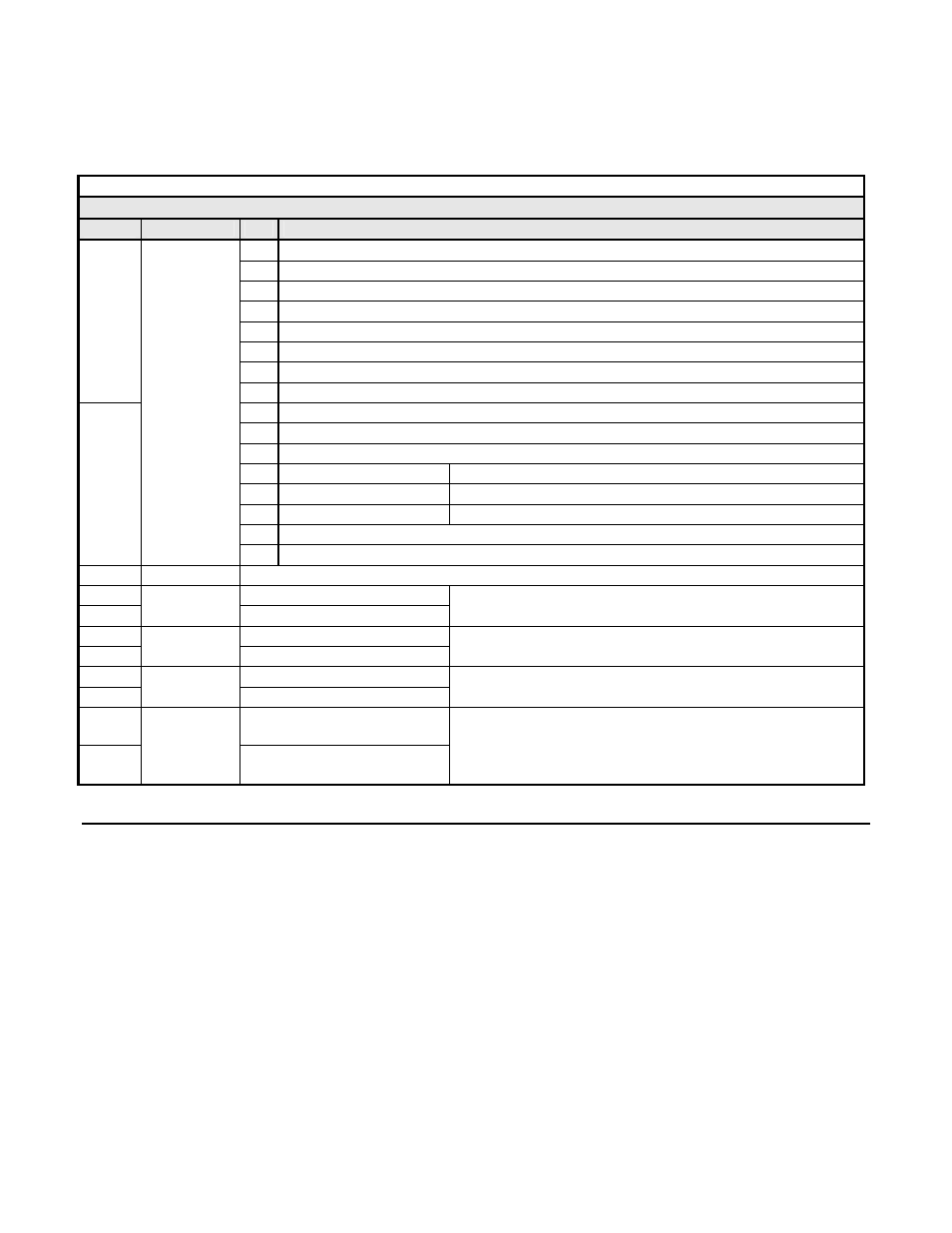
Fast I/O Input Data
The fast I/O input data area is used to transfer parameter data directly from the drive via a dual port RAM interface. The following table
details the functions of the fast I/O input data (Bytes 0 to 15). For detailed explanation of the terminal and multi-function inputs and
outputs, refer to the V7 Technical Manual.
Table 3.3 – 16 Word Input/Output Message Fast I/O Input Data
Fast I/O Input Data (V7 -> PROFIBUS-DP Master )
Byte
Function
Bit
Note
0 Running
1 @
Zero
Speed
2 @
Reverse
3 Reset
Signal
4 @
Frequency
Agree
5
Drive Ready (Rdy)
6 Minor
Fault
0
7 Major
Fault
8 OPE
Error
9 Fault
Restart
10 Local/Remote
11
Multi-function Output 1
1 = Close (terminal function dependent on setting of parameter n057)
12
Multi-function Output 2
1 = Close (terminal function dependent on setting of parameter n058)
13
Multi-function Output 3
1 = Close (terminal function dependent on setting of parameter n059)
14 Reserved
1
Drive
Status
15 Reserved
2 - 7
Reserved
Always 0
8
Frequency Reference MSB
9
Frequency
Reference
Frequency Reference LSB
0.01Hz
scaling is dependent on the setting of parameter n035
10 Output
Frequency
MSB
11
Output
Frequency
Output Frequency LSB
0.01Hz
scaling is dependent on the setting of parameter n035
12
Output Current MSB
13
Output
Current
Output Current LSB
0.1A
14 Pulse
Train
MSB
15
Frequency
Reference
Pulse Train
Terminal PR
Pulse train LSB
Parameter Access Area
This area is used to read and write parameter data from and to the drive. The PROFIBUS-DP Master completes the Parameter Access
command (output) message and waits for and then processes the data returned in the Parameter Access response (input) message. These
messages may contain 1 - 4 words of data. The handshaking byte is used to synchronize the communications between the PROFIBUS-DP
Master and the drive. This is necessary due to the additional time required for the drive to process the message. Refer to the Handshaking
section of this chapter for more information on handshaking. Note: Care must be taken when writing certain parameters to the V7 drive as
other parameters may be dependant on them. Control method, n002, maximum Frequency, n011, and Acc/Dec Scale Time, n018, are just a
few parameters whose setting will affect other parameter’s settings or ranges.. Refer to V7 MODBUS
®
Technical Manual for more
information.