Stub lengths are within specified limits, The network is terminated correctly, Troubleshooting c-9 – Yaskawa V7 PROFIBUS-DP User Manual
Page 61
Troubleshooting C-9
Stub Lengths Are Within Specified Limits
The total amount of measured linear cable allowed between the point of the stub connection (from the main PROFIBUS-DP cable) to the
node connection on the line, along with the cumulative total or sum of all stub cable length(s) must not exceed the maximum specified.
When calculating stub lengths, include stub in the device itself. Use 1cm for each V7 drive. The following table and diagram specifies the
stub length requirements. DO NOT use stubs when the PROFIBUS-DP network is configured to operate at baud rates above
1.5Mbps
Table C.5 – PROFIBUS-DP Stub Length Specifications
Baud Rate
Total Capacitance for all Stubs
Total Stub Length
9.6 Kbps
15.0 nF
500 Meters
187.5 Kbps
3.0 nF
100 Meters
500.0 Kbps
1.0 nF
33 Meters
1.5 Mbps
0.6 nF
20 Meters
3.0 Mbps
0.2 nF
Approx. 0
6.0 Mbps
Stubs Not Allowed
Approx. 0
12.0 Mbps
Stubs Not Allowed
Approx. 0
There Are No More Than 32 Total Devices On Each Network Segment.
This means that only 31 physical devices can be connected on one PROFIBUS-DP network segment without a repeater.
Verify that there are no more than 31 physical nodes on the network segment, which includes all Master/PLC connections,
slave devices, and configuration nodes for all connections. If there are more than 31 devices, you must add a repeater
between the network segments to separate the devices into two separate copper buses. Note, the reason for using RS485
repeaters is for allowing more than 32 devices to talk to one Master PLC port, or there is a need to operate bus segments as
ungrounded with reference to each other, or the network segment exceeds the maximum length per the operating baud rate.
Up to nine (9) RS485 repeaters can be used in cascade (in-line).
The Network Is Terminated Correctly.
A PROFIBUS-DP network copper bus segment is based on an RS485 standard and requires two (2) and only two (2), termination resistors
of 120 ohms, ¼ watt, at each of the furthest ends of the PROFIBUS-DP cabling. Typically, a good place for the termination resistors to be
ON is at the PLC connector (only, if the network segment starts at that point) and, at the last device on the network segment. This is to keep
transmission signal distortion to a minimum along all sections of the network bus.
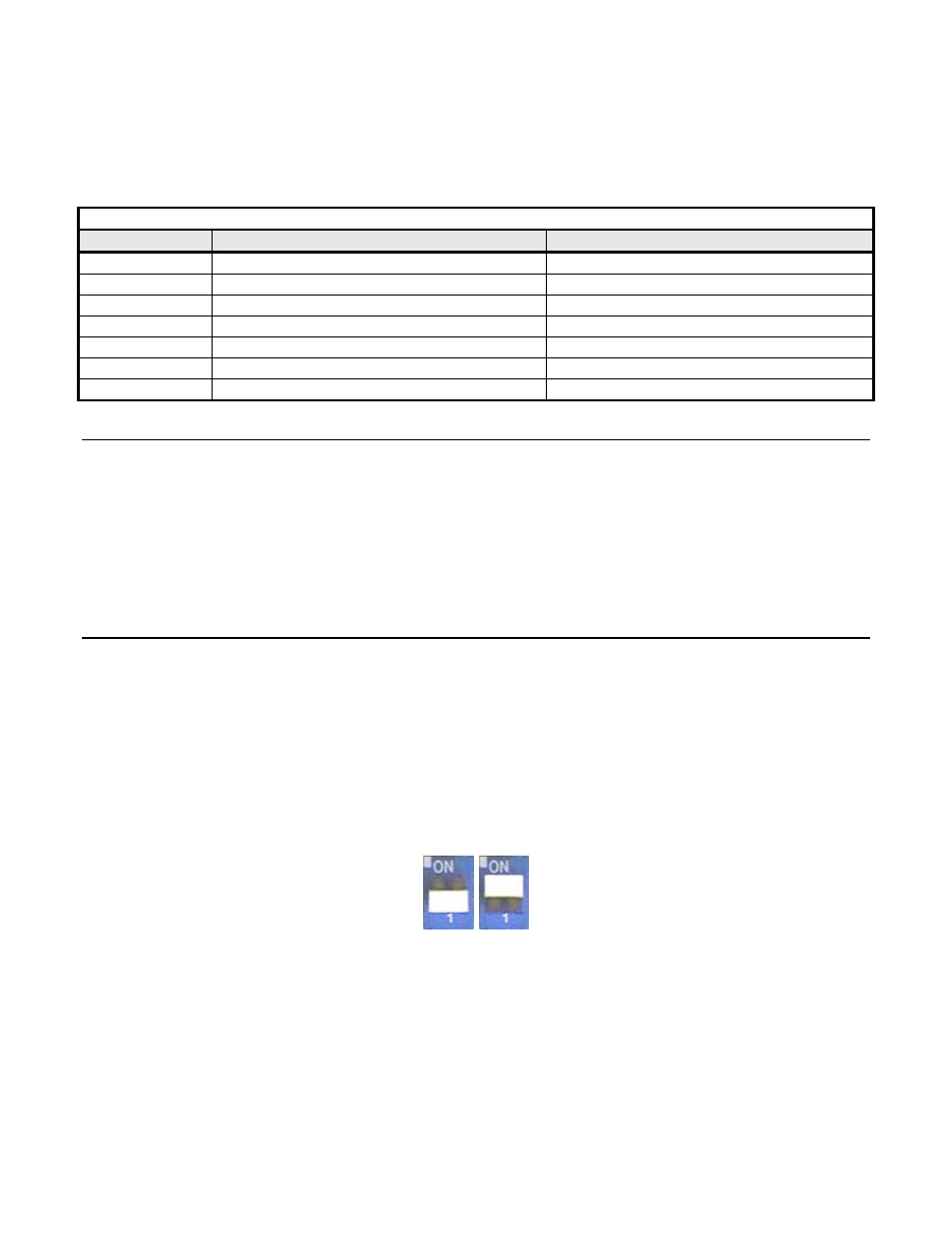
If the last device on the network is a drive, the termination switch on the PROFIBUS-DP Option may be used. Set the switch to
the ON position.
Active Termination Devices are the preferred method of terminating the network. They must be continually powered to function
correctly and must be used for transmission rates above 1.5 Mbps. The Siemens P/N for the Active Terminator Module is 6ES7
972-0DA00-0AA0.
Figure C.4 – V7 PROFIBUS-DP Option Termination Settings
OFF
ON