Installation, 1 hardware description, 1 switch front panel – PLANET WGSD-10020 User Manual
Page 29
User’s Manual of WGSD-10020 Series
2. INSTALLATION
This section describes the hardware features and installation of the Managed Switch on the desktop or rack mount. For easier
management and control of the Managed Switch, familiarize yourself with its display indicators, and ports. Front panel
illustrations in this chapter display the unit LED indicators. Before connecting any network device to the Managed Switch, please
read this chapter completely.
2.1 Hardware Description
2.1.1 Switch Front Panel
The unit front panel provides a simple interface monitoring the switch.
Figure 2-1& Figure
2-2
show the front panel of the
Managed Switches.
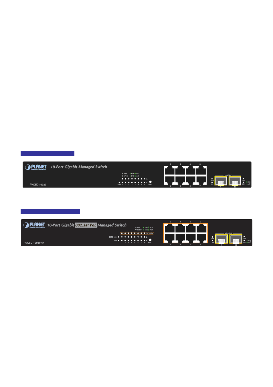
WGSD-10020 Front Panel
Figure 2-1
WGSD-10020 front panel.
WGSD-10020HP Front Panel
Figure 2-2
WGSD-10020HP front panel.
■ Gigabit TP interface
10/100/1000Base-T Copper, RJ-45 Twist-Pair: Up to 100 meters.
■ SFP slots
100/1000Base-X mini-GBIC slot, SFP (Small Factor Pluggable) transceiver module: From 550 meters (Multi-mode fiber),
up to 10/30/50/70/120 kilometers (Single-mode fiber).
■ Reset button
At the left of front panel, the reset button is designed for reboot the Managed Switch without turn off and on the power. The
following is the summary table of Reset button functions
:
29