Altera LVDS SERDES Transmitter / Receiver User Manual
Page 11
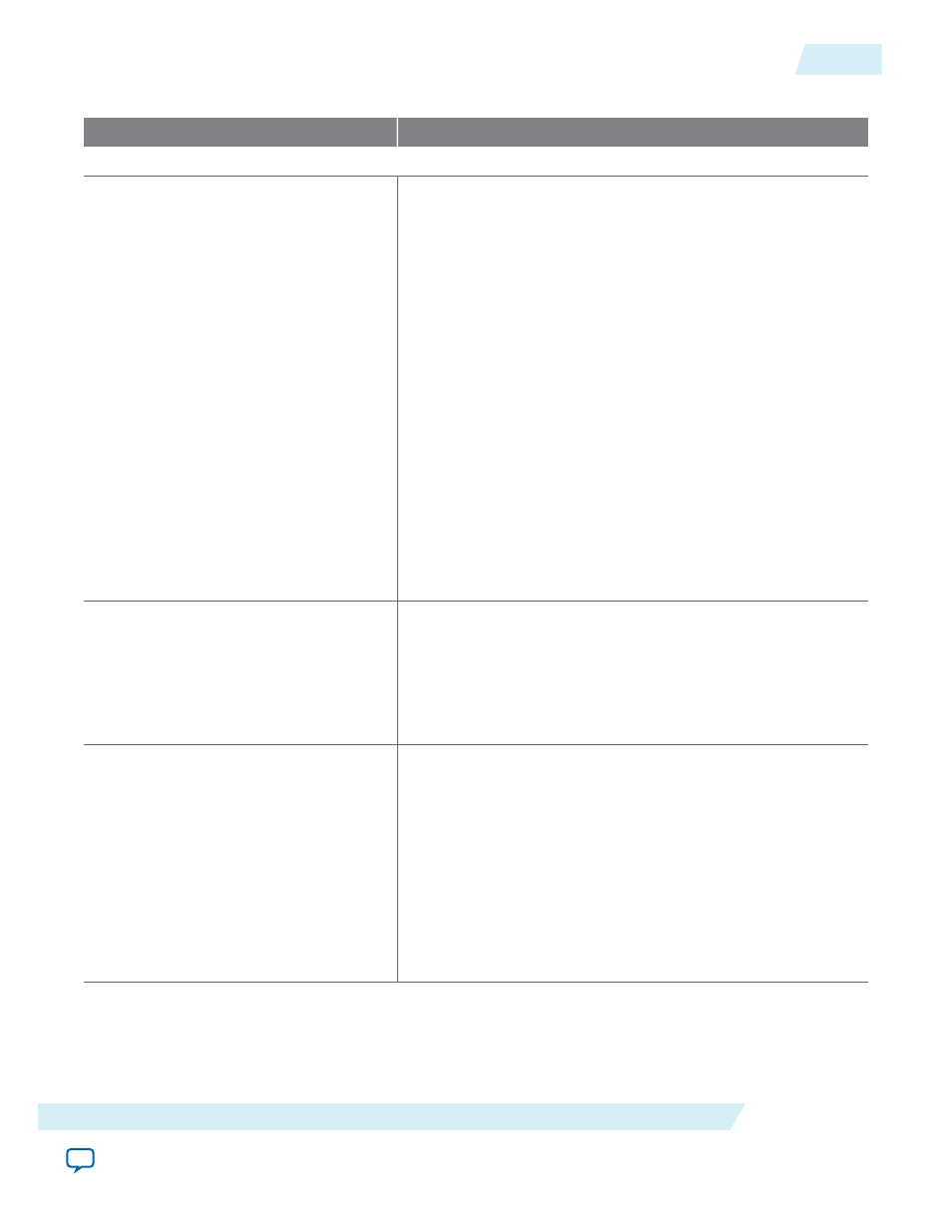
Table 5: ALTLVDS_TX Parameter Settings
Option
Description
General (page 3)
Implement Deserializer circuitry in
logic cells
Turn on this option to implement the SERDES circuitry in
logic cells. The transmitter starts its operation on the first fast
clock edge after the PLL is locked. This option is intended for
slow speeds. The byte alignment might be different from the
dedicated SERDES implementation.
Turn off this option to use the dedicated SERDES circuitry in
the device. When you implement the dedicated SERDES in the
LVDS transmitter, the SERDES connects to the LVDS
transmitter; therefore, the output of the transmitter cannot be
assigned to single-ended I/O standards.
This feature is supported in Arria GX, Arria II GX, Arria II GZ,
HardCopy II, HardCopy III, HardCopy IV, Stratix, Stratix GX,
Stratix II, Stratix II GX, Stratix III, and Stratix IV devices. In
Cyclone series, except Cyclone V devices, the SERDES is always
implemented in logic cells. Cyclone V devices contain
dedicated SERDES circuitry.
If you turn on this option, there is additional delay for the
tx_
outlock
signal to be stable after the
tx_locked
signal is
asserted. Perform gate-level simulation to determine the time
for the
tx_outclock
signal to stabilize.
What is the number of Channels?
Number of output channels available for the LVDS transmitter.
If the required number of channels is not available in the list,
type the desired number. For example, if the number of
channels is 44, the port created is
tx_out[43..0]
. The legal
values depend on the pins available in the device. For the legal
values for your device, refer to the relevant device handbook.
What is the deserialization factor?
Determines the number of parallel bits from the core that the
transmitter serializes and sends out. For example, if the
deserialization factor is 10 and the number of output channels
is 1, the transmitter serializes every 10 parallel bits into a single
output channel. If the deserialization factor is 10 and the
number of channels is 44, the port created is
tx_in[439..0]
.
For the valid deserialization factors for your device, refer to the
relevant device handbook.
When the
divide_by_factor
port shown in the parameter
editor is identical to the deserialization factor, the parameter
editor disables the 50/50 duty cycle for x5, x7, and x9 modes.
UG-MF9504
2014.12.15
ALTLVDS_TX Parameter Settings
11
LVDS SERDES Transmitter/Receiver IP Cores User Guide
Altera Corporation