Casella CEL CEL-393 User Manual
Page 51
recorder (F key), and then the required sweep selected on the CEL-393
by the appropriate command number followed by the A key. The filter
will then move to the all pass position, and await the initialisation of the
sweep by the E key (start scan) on the CEL-160. In this configuration,
the dwell time in each band is controlled by the CEL-160, and reference
should be made to its handbook for details of the optimum settings.
In order to provide both octave high bank and low bank sweeps, the
CEL-160 needs software with an issue number higher than 8.
The third octave high bank sweep is started by selecting code 0F on the
recorders key pad for all versions of the CEL-160.
The typical self noise levels in each analyser band are set out in Table
5, and these will determine the lowest value measureable in each band.
These relate to the B version only, and are typical values. For the D
version, and in critical situations with all versions, users are advised to
verify the noise floor of their particular unit by connecting a CEL-216 as
a dummy microphone with a shorting plug, and performing a frequency
sweep.
It is also necessary to appreciate that the filter and sound level meter
form an integral unit that may be operated only in conjunction with one
another. The Lin frequency path will therefore control the filter perform-
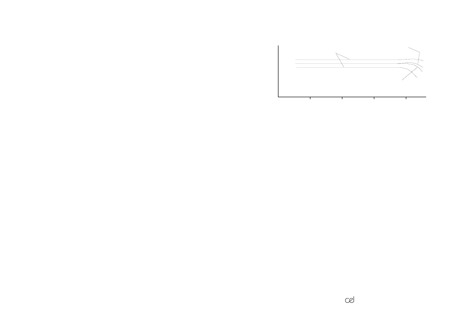
Figure 8 Typical frequency response, with permitted tolerances for
complete instrument
10Hz
100Hz
1kHz
10kHz
Linear response
All Lin on B version
Permitted tolerances
Frequency
Sound
Level
890020
393 Handbook
/47.