2 setup panels, 1 processor setup panel, Routing – Proel PRONET v.2.1 User Manual
Page 25: Setup panels, Processor setup panel
25
1.
Device ID and Device type;
2.
Device name;
3.
Group assignment;
4.
Current preset number and current preset name (F = Factory preset, U = user preset,
*
= some
parameter has been changed in the device and new modified preset has not be saved yet);
5.
Input signal LED and Input limit/comp and clip LED for left and right inputs;
6.
Output limit LED for loudspeaker output;
7.
Over Temperature protection LED indication: the device’s amplifier has run over the maximum
temperature range so the safety protection occurred and loudspeaker has been muted;
8.
Average Power Protection LED indication;
9.
Mute button (input mute control, not available for virtual devices);
10.
Edit panel button: open the DSP edit interface;
For a complete description of how protections work, please, refer to subwoofer’s user manuals.
5.2
Setup panels
5.2.1
Processor setup panel
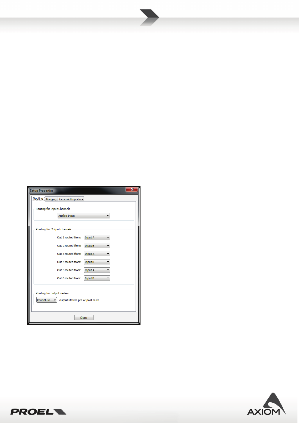
Fig.38 Routing page for PC240-PC260's Setup Panel .
Routing
In this setup page you can select the routing options for inputs (PC260 only), outputs and output meters.
Routing for input channels: this setup option is available only for PC260 and lets you select the input pair
connection to use between the analog input pair and the digital AES/EBU input pair. This option it is not
available for PC240.