Rear view – Rena T-750 User Manual
Page 8
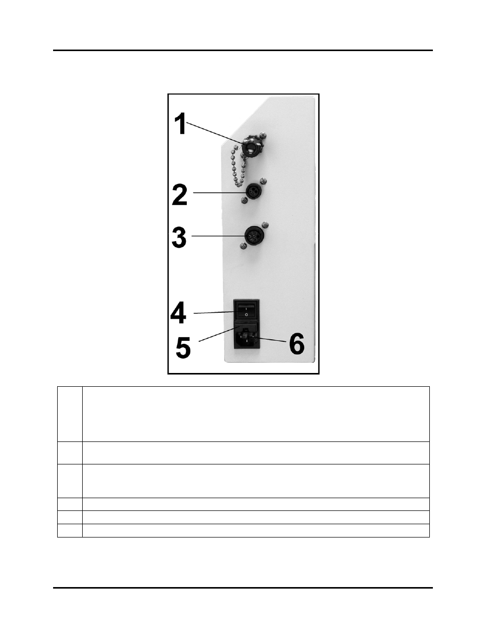
GETTING ACQUAINTED
Rear View
1
Emergency Stop Input & Jumper Plug – (SAFETY STOP) The safety circuit from
other external devices can be connected here.
When this input is opened the tabber will stop.
Important! If an external safety circuit is not being connected to this input, then the
Jumper Plug (supplied) must be connected, or the tabber transport will NOT run.
2
Emergency Stop Output – (EMERGENCY STOP-OUT) This connector permits the
T-750 to control the emergency stop function of an external device.
3
Tabber/Feeder Control Cable – (FEEDER) This connection allows the tabber to
start/stop the feeder. An appropriate cable and feeder must be used. When the EasyFeed
Lite feeder is connected, the T-750 can also synchronize the speed of the feeder.
4
Main Power Switch – This switch turns the T-750 On and Off.
5
Fuse – The main fuse (2.5A/250V) for the T-750 is located here.
6
Power Inlet Connection – The power cord is connected in here.
T-750 Tabber Operations Rev. 3/4/08
8